164 Rockwell Automation Publication 1769-IN088A-EN-P - February 2011
Chapter 3 I/O Memory Mapping
Fault State Word
Word 3, the fault state word, selects the hold last state or user-defined safe state
condition for each individual output on a system transition from Run to Fault.
Fault Value Word
(1)
The fault value word, word 4, is used to program the fault state value (0 = Off,
1 = On). Each output is individually configurable for on or off.
Program to Fault Enable Bit (PFE)
Word 0, bit 0, allows the selection of which data value, the program or fault value,
to apply to the output if a system in Program mode undergoes a system fault,
resulting in a change to the Fault mode.
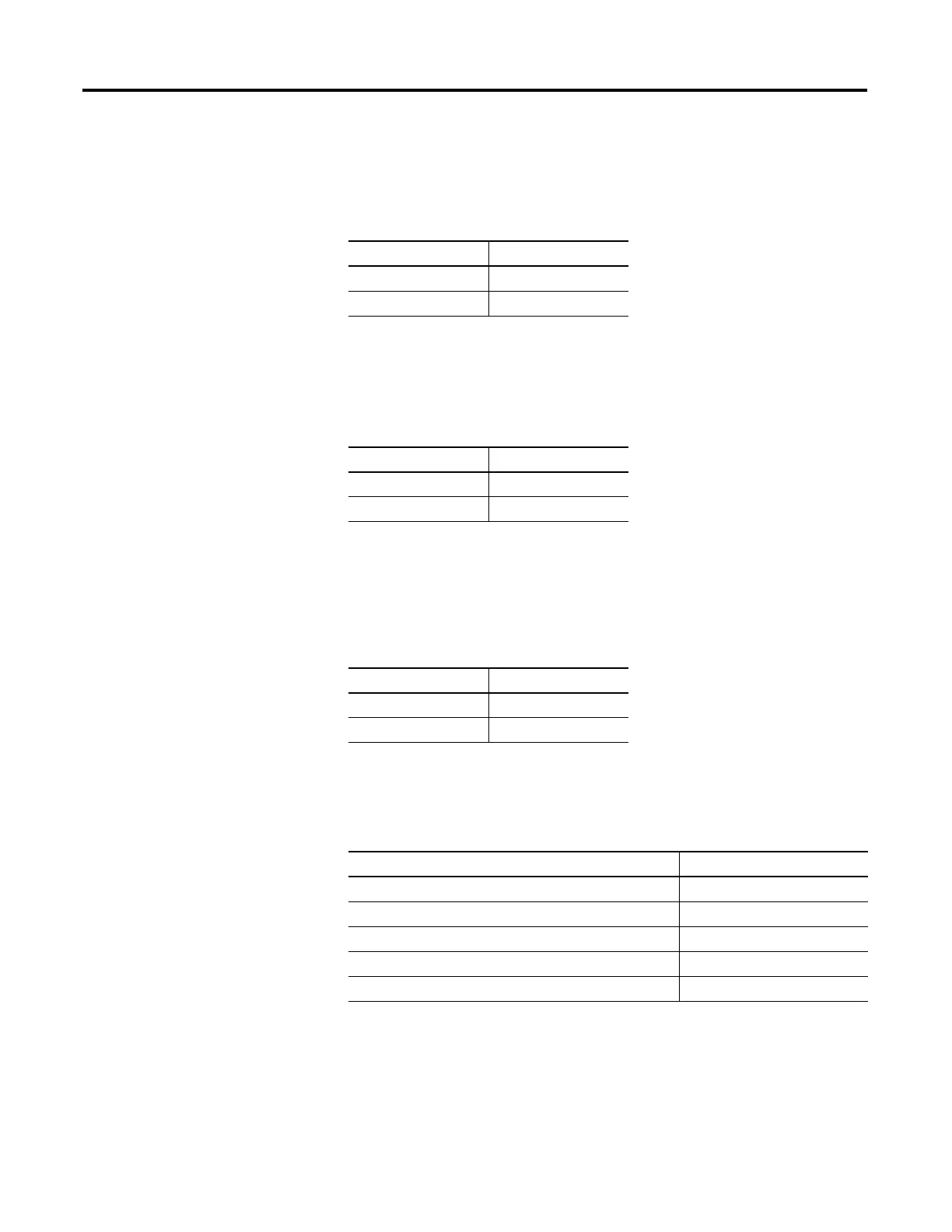
Module Default Condition
(1)
The modules default condition is all zeros.
Condition Bit Setting
User-defined Safe State 0
Hold Last State 1
Value Bit Setting
Off 0
On 1
Value Applied Bit Setting
Program 0
Fault 1
(1) TTL outputs are inverted (On = 1 = logic low voltage = 0…0.4V dc; Off = 0 = logic high voltage = 4.5…5.5V dc).
Use a NOT instruction in the ladder program to convert to traditional True = High logic.
Word or Bit Affected Condition Applied
Word 0, Bit 0 Program-to-fault Enable Program Value
Word 1 Program State User-defined Safe State
Word 2 Program Value Off
Word 3 Fault State User-defined Safe State
Word 4 Fault Value Off
 Loading...


