Rockwell Automation Publication 440R-UM010C-EN-P - September 2016 19
Power, Ground, and Wire Chapter 3
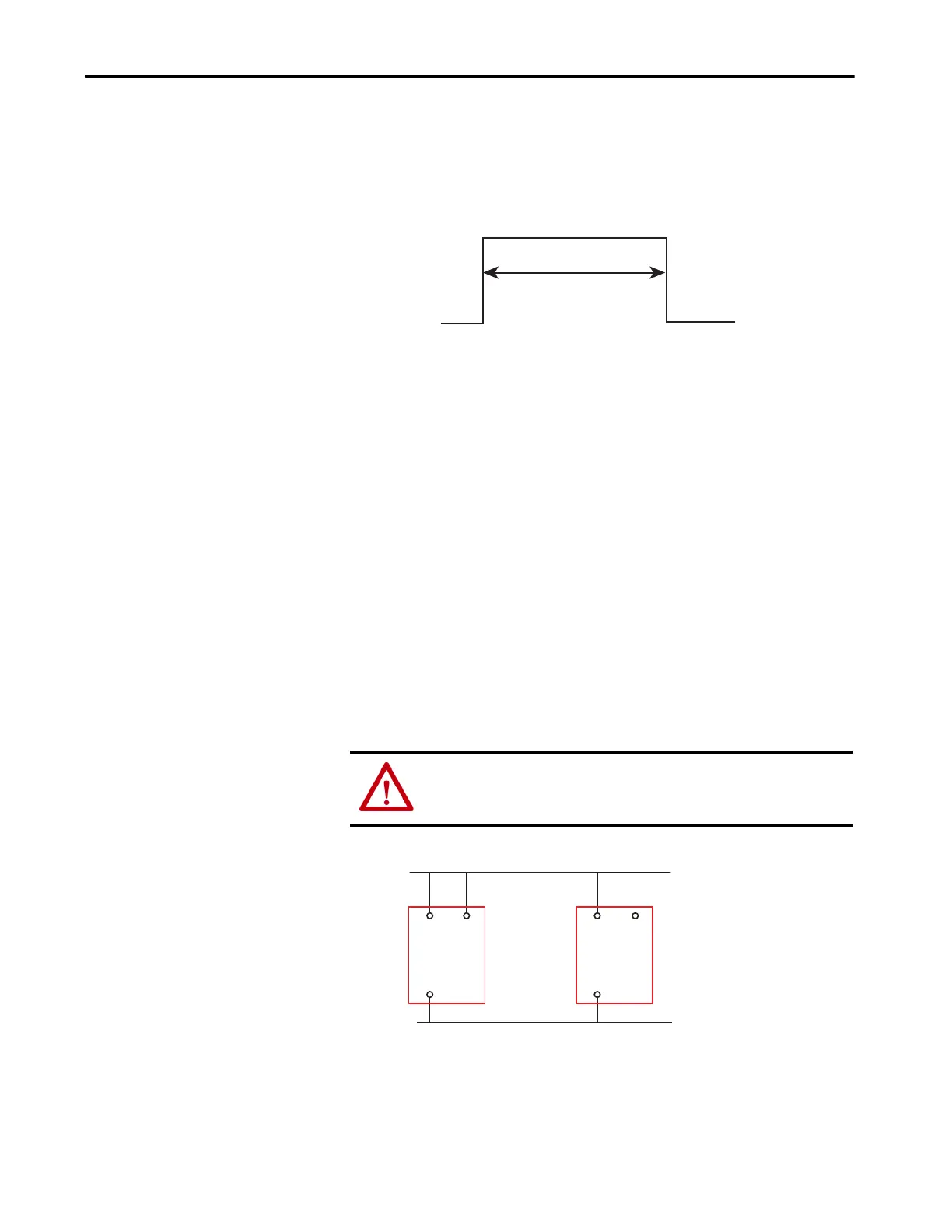
Lock and Unlock Signals
The GLT safety relay is designed to ignore incidental actuations or stuck
conditions on the Lock and Unlock inputs. The lock and unlock signals must
be actuated for a duration of 0.25...3 seconds. The GLT safety relay ignores
signals durations that are too short or too long.
Figure 14 - Required Signal Duration
Retriggerable Input
The retriggerable input is either left open for non-retriggerable operation or
connected directly to the +24V DC supply for retriggerable operation. During
configuration, the GLT safety relay reads the status of the input to determine
whether to apply the function to the safeguarding input. The retriggerable
input only works with Logic Setting 5, 6, 7, and 8. Retriggerable operation is
often used when long delay times are configured in the GLT safety relay.
When terminal B2 is not connected to +24V DC, the safeguarding input
device must be held open for the full duration of the timed delay cycle. If the
input device is reclosed during the timing cycle, the PWR/Fault indicator is
green with five red flashes. To clear the fault indication, cycle the input device
(OFF then ON) after the completion of the timing cycle.
When terminal B2 is connected to +24V DC, the safeguarding input device
can be closed before the full duration of the timed delay cycle, and this action
resets the timer. When the input is reclosed during the timing cycle, the
immediate outputs turn back ON immediately
Figure 15 - Retriggerable Input Wiring
+24V DC
250ms to 3000ms
24V DC Com
WARNING: You must confirm that the reclosing or resetting of an
interlocking safeguard or E-stop device does not initiate hazardous machine
operation.
+24V DC
24V DC Com
GLT
B2
A1
A2
GLT
B2
A1
A2

 Loading...


