Rockwell Automation Publication 440R-UM010C-EN-P - September 2016 31
Diagnostic Status Indicators and Troubleshooting Chapter 5
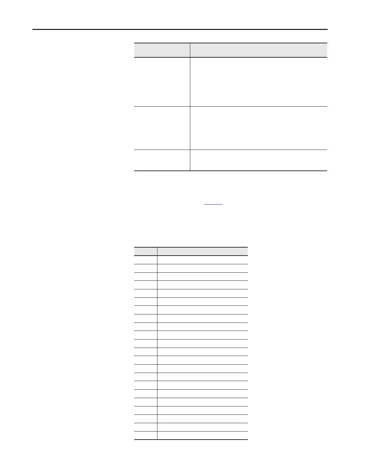
Additional Diagnostics
The IN1 status indicator flashes additional information regarding faults that
the GLT safety relay detects. Ta ble 8
provides a description of the fault for each
of the flash rates. You must inspect wiring, measure the voltages/waveforms at
the respective terminals, check the configuration switches, and if necessary,
report the fault to the factory.
Table 8 - Flash Rate Fault Description
Flashing red 6 times IN1 is flashing 7 times
• Short circuit fault on terminal 14 to ground or
• Short circuit fault on terminal 24 to 24V with pulse testing
IN1 is flashing 8 times
• Short circuit fault on terminal 24 to ground or
• Short circuit fault on terminal 24 to 24V with pulse testing or
• Short circuit fault from terminal 14 to terminal 24 with pulse testing.
Correct the fault and cycle power to the GLT safety relay.
Flashing red 9 times IN1 is flashing 9 times
• Short circuit from terminal 51 to L61
• Open circuit on terminal 51 or L61
IN1 is flashing 10 times
• Short circuit fault on terminal 51 or L61 to ground or
• Short circuit fault on terminal 51 or L61 to 24V.
Correct the fault and cycle the power to the GLT safety relay.
Flashing red 10 times IN1 is flashing 33 times
• The supply voltage exceeded 26.4V DC - Overvoltage
Correct the power supply and cycle the power.
Power/Status Status
Indicator
Status/Faults
Flashes Description
0No fault
5S11 pulse test fault
6S21 pulse test fault
7 OSSD1 fault (terminal 14)
8 OSSD2 fault (terminal 24)
9 Terminal L61
10 Terminal 51
11 SPI fault
12 L11 fault
13 Guard locking system differs from EPROM
14 Configuration switches differ from EPROM
15 EPROM fault
17 Compare state fault
22 Cross fault
23 Wiring at B2 differs from EPROM
24 Input is open when gate is locked
25 Switch overflow
30 S12 fault
31 S22 fault
32 Main transistor fault
33 Overvoltage
34 S44 or S54 fault

 Loading...


