Rockwell Automation Publication 2198-IN021A-EN-P - June 2020 3
Kinetix 5300 Single-axis EtherNet/IP Servo Drives Installation Instructions
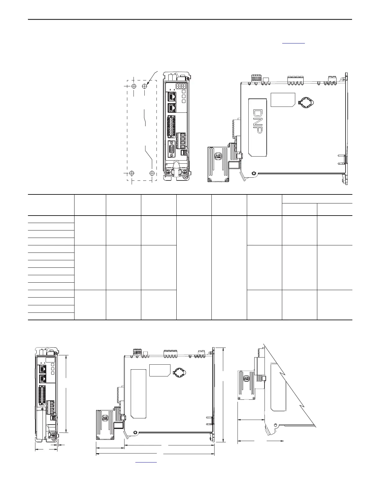
Product Dimensions
Included in this figure are the drill hole patterns for standalone drives. Refer to the Kinetix 5300 Servo Drives User Manual, publication 2198-UM005, for multi-axis drill-hole
patterns.
Kinetix 5300 Drives with 2198-K53CK-D15M Connector Kit
Kinetix 5300 Drives with 2198-K53CK-D15M Connector Kit
Refer to Kinetix Servo Drives Technical Data, publication KNX-TD003, for motor/actuator compatibility with the 2198-K53CK-D15M connector kit and product dimensions.
Kinetix 5300 Drive
Cat. No.
Frame
A
mm (in.)
B
mm (in.)
C
mm (in.)
D
mm (in.)
E
mm (in.)
Drill Hole Patterns
(1)
(1) Hole spacing is measured in millimeters and not converted to inches to avoid errors due to rounding.
F
mm
G
mm
2198-C1004-ERS
1 50 (1.97) 175 (6.89)
204 (8.03) 265 (10.43)
215 (8.46) 193.68 4.51
2198-C1007-ERS
2198-C4004-ERS
2198-C4007-ERS
2198-C1015-ERS
2 55 (2.16) 225 (8.86) 265 (10.43) 243.84 5.00
2198-C1020-ERS
2198-C2030-ERS
2198-C4015-ERS
2198-C4020-ERS
2198-C4030-ERS
2198-C2055-ERS
3 85.2 (3.35) 250 (9.84) 294 (11.57) 273.70 0.0
2198-C2075-ERS
2198-C4055-ERS
2198-C4075-ERS
MBRK
W
V
U
1
10
1
2
MFB
F
0.0
0.0
G
52.50
34.00
Dimensions are in mm
2198-C1004-ERS
Drive is Shown
Applies to
Only
Frame 3
Hole spacing is measured in millimeters
and not converted to inches to avoid
errors due to rounding.
65.0
(2.56)
E
A
3.0
(0.12)
B
D
265
(10.43)
65.0
(2.56)
MBRK
W
V
U
1
10
1
2
C
Dimensions are in mm (in.)
Frame 1 Servo Drive
2198-K53CK-D15M
Feedback Connector Kit
Mounted on Frame 1 Drive
2198-K53CK-D15M
Feedback Connector Kit
Mounted on a Frame 2 or 3 Drive

 Loading...


