6 Rockwell Automation Publication 2198-IN021A-EN-P - June 2020
Kinetix 5300 Single-axis EtherNet/IP Servo Drives Installation Instructions
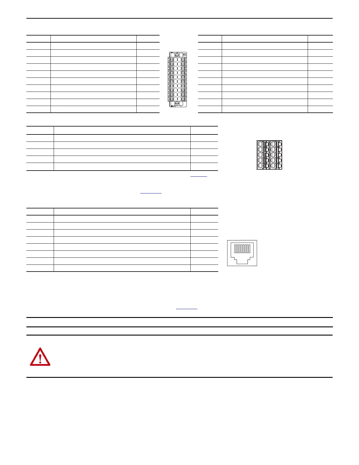
Digital Inputs and Auxiliary Feedback Connector Pinout
Safe Torque-off (STO) Connector Pinout
The 2198-Cxxxx-ERS drives ship with the safe torque-off function enabled. Connect the safe torque-off inputs to a safety circuit or install bypass wiring to enable motion.
Refer to the Kinetix 5300 Servo Drives User Manual, publication 2198-UM005
, for more information.
Ethernet Communication PORT1 and PORT2 Pinout
Wiring Requirements
Wire must be copper with 75 C (167 F) minimum rating. Phasing of AC input power is arbitrary and earth ground connection is required for safe and proper operation.
Refer to Kinetix 5300 Single-axis EtherNet/IP Servo Drives User Manual, publication 2198-UM005
, for interconnect diagrams.
Pin Description Signal Pin Description Signal
1 24V current-sinking fast input #1 IN1 11 24V current-sinking fast input #3 IN3
2 I/O common for customer-supplied 24V supply COM 12 I/O common for customer-supplied 24V supply COM
3 24V current-sinking fast input #2 IN2 13 24V current-sinking fast input #4 IN4
4 I/O common for customer-supplied 24V supply COM 14 I/O common for customer-supplied 24V supply COM
5 I/O cable shield termination point SHLD 15 I/O cable shield termination point SHLD
6 Channel AM Differential Input + AM+ 16 Channel AM Differential Input – AM–
7 Channel BM Differential Input + BM+ 17 Channel BM Differential Input – BM–
8 Channel IM Differential Input + IM+ 18 Channel IM Differential Input – IM–
9 Encoder 5V power output EPWR_5V 19 Auxiliary common AUX_COM
10 Auxiliary feedback cable shield termination point SHLD 20 Auxiliary feedback cable shield termination point SHLD
STO Pin
(1)
(1) STO is enabled by default, with no terminations. Refer to the Kinetix 5300 Servo Drives User Manual, publication 2198-UM005, to wire safe torque off bypass jumper or to wire to the upstream relay as required.
Description Signal
1 / 6 Safety bypass plus signal. Connect to both safety inputs to disable the STO function SB+
2 / 7 Safety bypass minus signal. Connect to safety common to disable the STO function SB-
3 / 8 STO input 1 (SS_IN_CH0) S1
4 / 9 STO input common (SCOM) SC
5 / 10 STO input 2 (SS_IN_CH1) S2
Port Pin Description Signal
1 Transmit port (+) data terminal TD+
2 Transmit port (–) data terminal TD–
3 Receive port (+) data terminal RD+
4– –
5– –
6 Receive port (–) data terminal RD–
7– –
8– –
IMPORTANT
The National Electrical Code and local electrical codes take precedence over the values and methods provided.
ATTENTION: To avoid personal injury and/or equipment damage, observe the following:
• Make sure installation complies with specifications regarding wire types, conductor sizes, branch circuit protection, and disconnect devices. The
National Electrical Code (NEC) and local codes outline provisions for safely installing electrical equipment.
• Use motor power connectors only for connection purposes. Do not use them to turn the unit on and off.
• Ground shielded power cables to prevent potentially high voltages on the shield.
1
5
6
SB+
SB-
S1
SC
S2
10
SB+
SB-
S1
SC
S2

 Loading...


