Rockwell Automation Publication 2198-IN021A-EN-P - June 2020 7
Kinetix 5300 Single-axis EtherNet/IP Servo Drives Installation Instructions
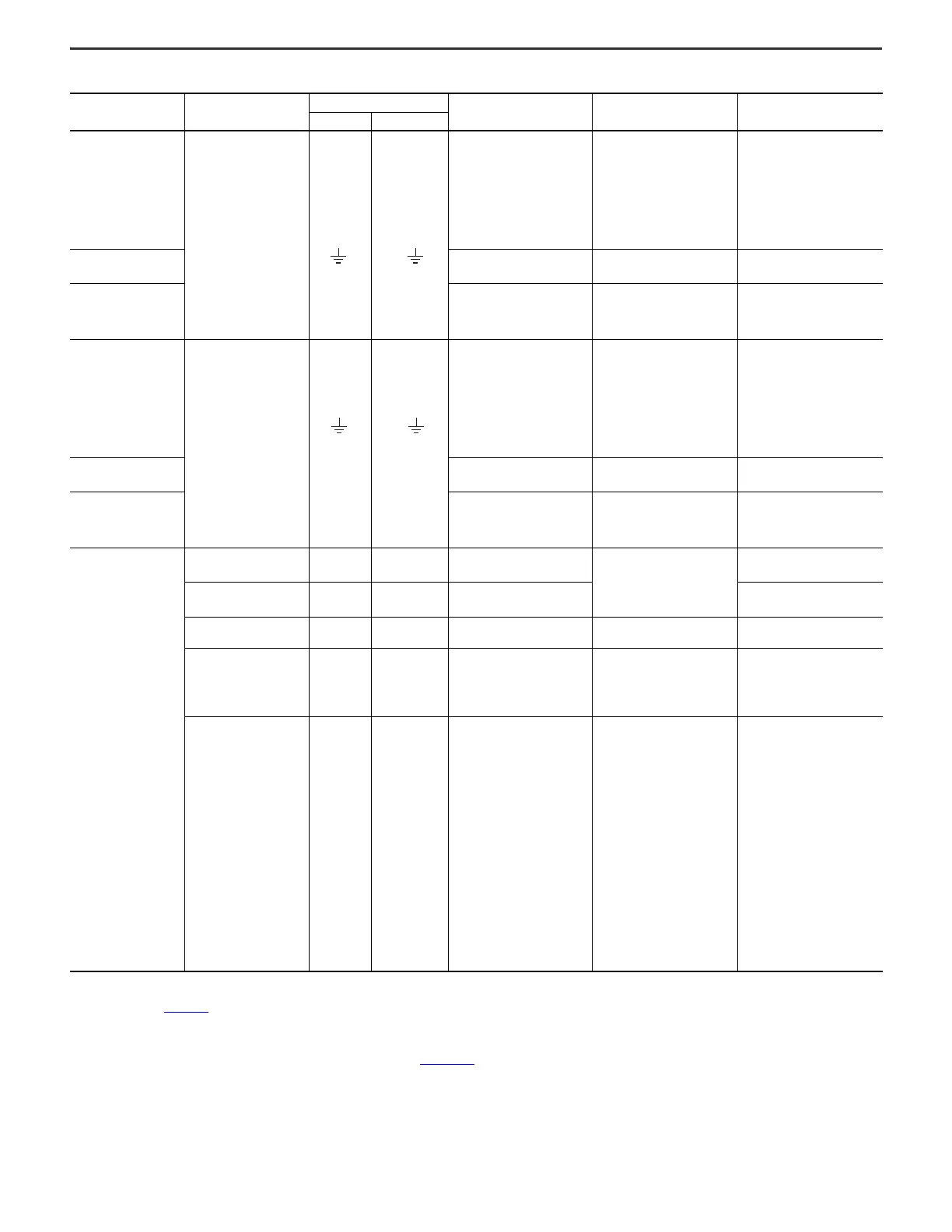
Kinetix 5300 Drive Power and I/O Wiring Requirements
See Kinetix Motion Accessories Specifications Technical Data, publication KNX-TD004
, for cable specifications.
Kinetix 5300 Drive
Cat. No.
Description
Connects to Terminals
Wire Size
mm
2
(AWG)
Strip Length
mm (in.)
Torque Value
N•m (lb•in)
Pin Signal
2198-C1004-ERS
2198-C1007-ERS
2198-C1015-ERS
2198-C1020-ERS
2198-C4004-ERS
2198-C4007-ERS
2198-C4015-ERS
2198-C4020-ERS
2198-C4030-ERS
AC input
power
0.2…2.5
(24…12)
8.0
(0.31)
0.5…0.6
(4.4…5.3)
2198-C2030-ERS
0.2 … 6.0
(24 … 10)
10.0
(0.39)
0.5 … 0.6
(4.4 … 5.3)
(1)
(1) For 10 AWG conductors, use 0.7…0.8 N•m (6.2…7.1 lb•in) of torque.
2198-C2055-ERS
2198-C2075-ERS
2198-C4055-ERS
2198-C4075-ERS
0.75…16
(18…6)
12.0
(0.47)
1.7 … 1.8
(15.0…15.9)
2198-C1004-ERS
2198-C1007-ERS
2198-C1015-ERS
2198-C1020-ERS
2198-C4004-ERS
2198-C4007-ERS
2198-C4015-ERS
2198-C4020-ERS
2198-C4030-ERS
Motor power
Motor power cable depends on
motor/drive combination.
0.2…2.5
(24…12)
8.0
(0.31)
0.5…0.6
(4.4…5.3)
2198-C2030-ERS
0.2 … 6.0
(24 … 10)
10.0
(0.39)
0.5 … 0.6
(2)
(4.4 … 5.3)
(2) The wire size, strip length, and torque specifications shown here apply to the single-axis connector that ships with the drive. For the shared-bus connector specifications, refer to the Kinetix 5300 Servo Drives User
Manual, publication 2198-UM005
.
2198-C2055-ERS
2198-C2075-ERS
2198-C4055-ERS
2198-C4075-ERS
0.75…16
(18…6)
12.0
(0.47)
1.7 … 1.8
(15.0…15.9)
2198-C1004-ERS
2198-C1007-ERS
2198-C1015-ERS
2198-C1020-ERS
2198-C2030-ERS
2198-C2055-ERS
2198-C2075-ERS
2198-C4004-ERS
2198-C4007-ERS
2198-C4015-ERS
2198-C4020-ERS
2198-C4030-ERS
2198-C4055-ERS
2198-C4075-ERS
PELV 24V power
(2)
(single-axis connector)
1
2
24V+
24V-
0.2…2.5
(24…12)
7.0 (0.28)
0.5…0.6
(4.4…5.3)
Brake power
1
2
MBRK+
MBRK-
0.14…1.5
(28…16)
(3)
(3) Motor brake wires are part of the 2090-Series motor cable.
0.22…0.25
(1.9…2.2)
Shunt resistor —
DC+
SH
0.2…2.5
(24…12)
8.0 (0.31)
0.5…0.6
(4.4…5.3)
Safety
ST0-1/6
ST0-2/7
ST0-3/8
ST0-4/9
ST0-5/10
SB+
SB-
S1
SC
S2
0.2…1.5
(24…16)
10.0 (0.39)
N/A
(4)
(4) This connector uses spring tension to hold wires in place.
Digital inputs and
Auxiliary feedback
1
2
3
4
5
6
7
8
9
10
11
12
13
14
15
16
17
18
19
20
IN1
COM
IN2
COM
SHLD
AUX_AM+
AUX_BM+
AUX_IM+
Reserved
SHLD
IN3
COM
IN4
COM
SHLD
AUX_AM-
AUX_BM-
AUX_IM-
EPWR_5V
SHLD
0.2…1.5
(24…16)
10.0 (0.39)
N/A
(4)

 Loading...


