8 Rockwell Automation Publication 2198-IN021A-EN-P - June 2020
Kinetix 5300 Single-axis EtherNet/IP Servo Drives Installation Instructions
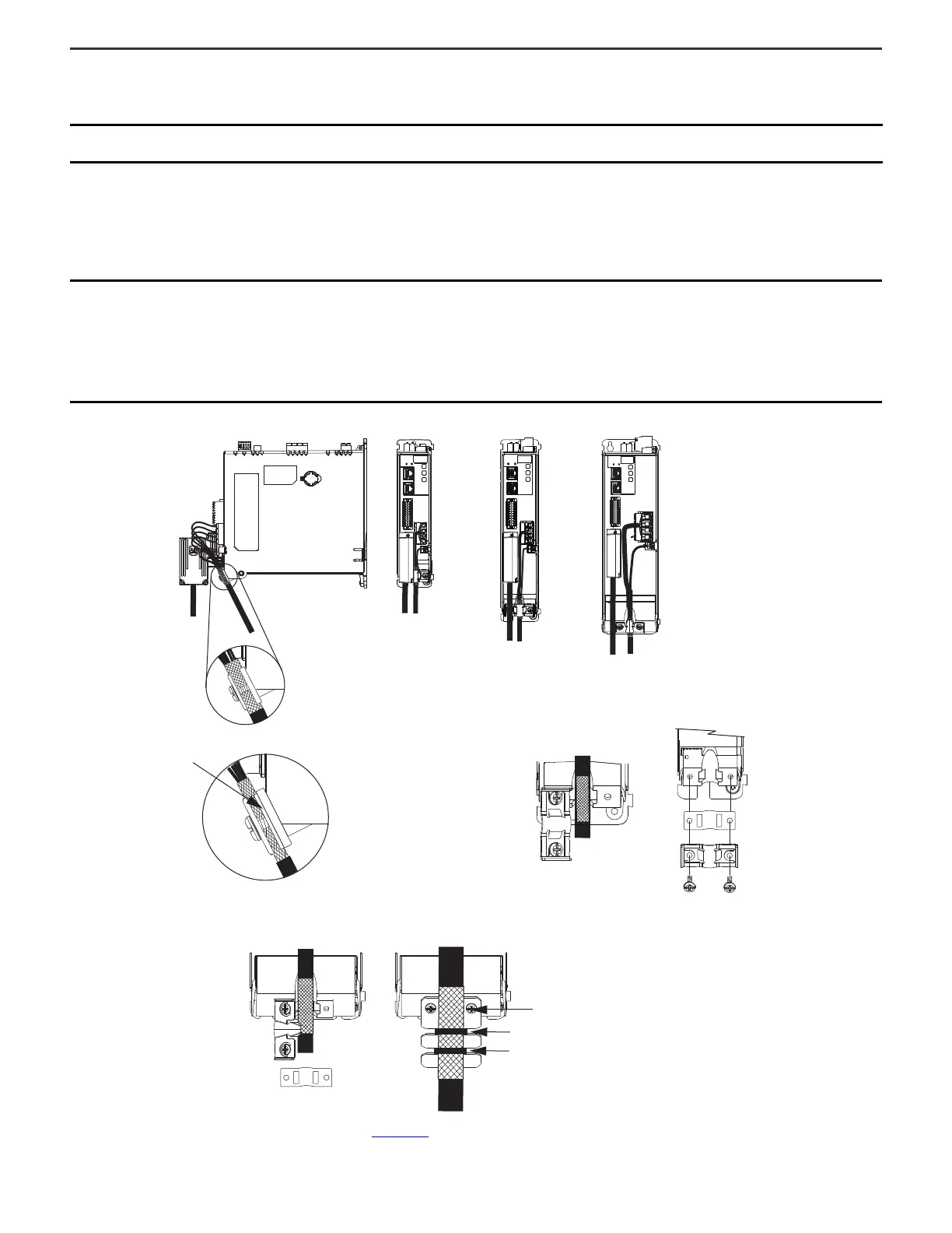
Attach the Motor Cable Shield Clamp
A shield clamp and two screws are supplied with each Kinetix 5300 drive. Use the clamp to bond the motor cable shield-braid to chassis ground.
Allen-Bradley Motors and Actuators
A clamp spacer is included with the drive for motor power/brake cable diameters that are too small for a tight fit within the drive clamp alone. A clamping plate is provided
with frame 3 drives for cables too large to fit within the standard shield clamp.
Cable Clamp Attachment
Refer to the Kinetix 5300 Servo Drives User Manual, publication 2198-UM005
, for detailed information on wiring the 2198-K53CK-D15M feedback connector kit and attaching
the motor power/brake shield clamp.
IMPORTANT
• Loosen the screw, if needed, until you can start threading both clamp screws with the cable shield under the clamp.
• Make sure the cable clamp tightens around the cable shield and provides a high-frequency bond between the cable shield and the drive chassis.
IMPORTANT
If the power/brake cable shield has a loose fit inside the shield clamp, insert the clamp spacer between the shield clamp and the drive to reduce
the clamp diameter. When the clamp screws are tight, 2.0 N•m (17.7 lb•in), the result must be a high-frequency bond between the cable shield and
the drive chassis.
If the frame 3 cable is too large to fit within the standard shield clamp, substitute the standard clamp for the frame 3 clamping plate.
The standard shield clamp screws are reused on the frame 3 clamping plate.
Apply two tie-wraps around the cable shield and clamping plate, to provide a high-frequency bond between the cable shield and the drive chassis.
MBRK
W
V
U
1
10
1
2
MFB
MBRK
1
10
1
2
MFB
U
V
W
1
2
1
10
W
V
U
MBRK
MFB
Standard Shield
Clamp Compressed
Around Shield
(no spacer required)
Insert the clamp spacer when
the cable diameter is smaller
than the drive clamp alone.
Shield Clamp
Clamp Screws
2.0 N•m (17.7 lb•in.)
Service Loops
Frame 1
Servo Drive
Frame 2
Servo Drive
Frame 3
Servo Drive
Clamp Spacer Added
(small diameter cable)
Clamping Plate for Large
(2)
Diameter Cables
(applies to frame 3 only)
Standard Shield Clamp
(frame sizes 1 and 2)
Frame 3
Servo Drive
Standard Shield Clamp
(frame 3)
Substitute the Frame 3 clamping plate
when the cable diameter is too large for
the standard shield clamp.
Apply tie-wraps to
achieve high-frequency
bond with clamp.
(1) The clamp spacer is included in 2198-CONKIT-PWRxx connector sets with frame 1, 2, and 3 drives.
(2) The clamping plate is included in only the 2198-CONKIT-PWR75 connector set with frame 3 drives.
Connector Kit
2198-K53CK-D15M
Clamp Screws
Frame 1 and 2
Servo Drives
Clamp Spacer (if needed)
(1)
Clamp Spacer
(1)
(if needed)

 Loading...


