6 Rockwell Automation Publication 2198-IN016B-EN-P - October 2018
Kinetix 5700 DC-bus Conditioner Module
Connector Data
Lug spacers are needed only when wiring both external DC-bus and active shunt connections to
the lug studs. Two types of lug covers are provided, one for systems with external DC-bus or
active shunt wires attached and one without.
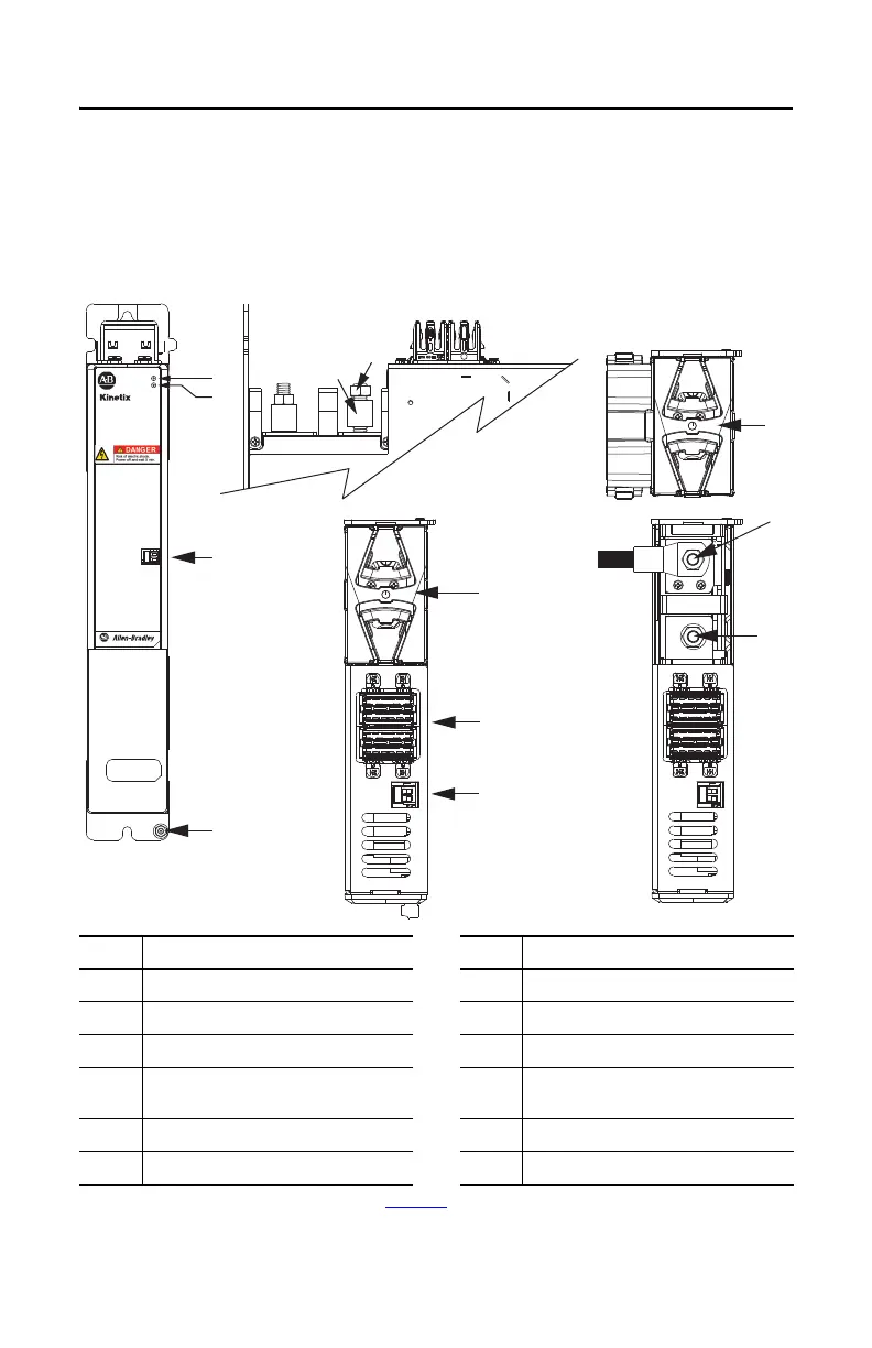
DC-bus Conditioner Module Features and Indicators
Item Description Item Description
1 Ground stud 7 DC-bus (DC) connector
2 Module status (MS) connector 8 24V control input power (CP) connector
3DC Bus status indicator
(1)
(1) See the Kinetix 5700 Servo Drives User Manual, publication 2198-UM002, for information on troubleshooting the Module and DC Bus status
indicators.
9 DC– M8 stud (external DC-bus)
4 Module status indicator
(1)
10
DC+ M8 stud (external DC-bus), shown with
wire lug
5 Stud/lug cover with wires
(2)
(2) This example shows the lug cover oriented for wires exiting to the left (adjacent module is on the far left of the drive configuration). Rotate lug
cover 180° when wires exit to the right (adjacent module is on the far right of the drive configuration).
11 M8 hex nut
6 Stud cover without wires 12 Lug spacer
MODULE
STATUS
MOD
DC BUS
8
24V–
24V+
2
3
4
1
7
6
24V–
24V+
10
9
12
11
5
5700
2198-DCBUSCOND-RP312
DC-bus Conditioner Module
(front view)
2198-DCBUSCOND-RP312
DC-bus Conditioner Module
(top views)
2198-DCBUSCOND-RP312
DC-bus Conditioner Module
(side view, lug cover removed)

 Loading...


