Rockwell Automation Publication 2198-IN016B-EN-P - October 2018 7
Kinetix 5700 DC-bus Conditioner Module
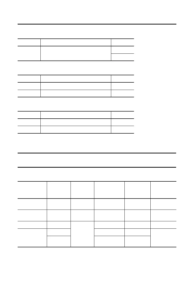
DC Bus (DC) Connector Pinout
Control Input Power (CP) Connector Pinout
Module Status (MS) Connector Pinout
Wiring Requirements
DC-bus Conditioner Module Wiring Requirements
DC Pin Description Signal
Bus link DC bus connections
DC–
DC+
CP Pin Description Signal
1 24V power supply, customer-supplied 24V+
2 24V common 24V–
MS Pin Description Signal
1 Module status relay output + RELAY+
2 Module status relay output – RELAY–
IMPORTANT The National Electrical Code and local electrical codes take precedence over the values and
methods provided.
Connector
Description
Pin Signal
Recommended
Wire Size
mm
2
(AWG)
Strip Length
mm (in.)
Torque Value
N•m (lb•in)
Module Status
MS-1
MS-2
RELAY+
RELAY–
0.14…1.5
(28…16)
7.0 (0.28)
0.22…0.25
(1.9…2.2)
PELV/SELV
24V power (plug)
CP-1
CP-2
24V+
24V–
0.5…2.5
(20…14)
7.0 (0.28)
0.22…0.25
(1.9…2.2)
DC-bus power Bus-bar
DC–
DC+
N/A
(1)
N/A
(1)
(1) DC bus connections are always made from drive-to-drive over the shared-bus connection system. These terminals do not receive discrete wires.
N/A
(1)
DC-bus studs
Bus-bar N/A N/A
18 (156)
Lugs
53.5 (1/0 AWG) 104 A
152 (300 kcmil) 208 A
N/A
(2)
(2) Strip length for the DC-bus studs depend on the customer-supplied lugs.

 Loading...


