Publication 2711P-UM001D-EN-P - September 2005
Install and Replace Components 5-11
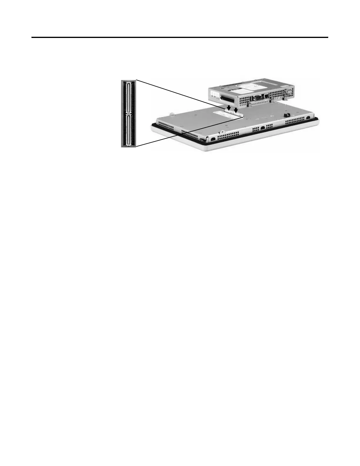
7. Position the new logic module over the new display module so
that the connectors align.
8. Push down on the logic module until firmly seated.
9. Tighten the six captive screws that secure the logic module to
the display module to a torque of 0.68 Nm
(6 to 8 in-lb).
10. Attach the communication module (if necessary) and tighten the
four screws to a torque of 0.68 Nm (6 to 8 in-lb).

 Loading...


