Publication 2711P-UM001D-EN-P - September 2005
5-6 Install and Replace Components
Install or Replace a
Communication Module
This section shows how to install and replace a communication
module. The communication module installs over the logic module.
The communication modules are available as separate catalog
numbers for specific communication protocols. The installation is the
same for all modules regardless of the communication type.
Install or Replace Communication Module on 700-1500 Terminals
To install a communication module:
1. Disconnect power from the terminal.
2. If the terminal is removed from panel, set the terminal, display
side down, on a clean, flat, stable surface to prevent scratches.
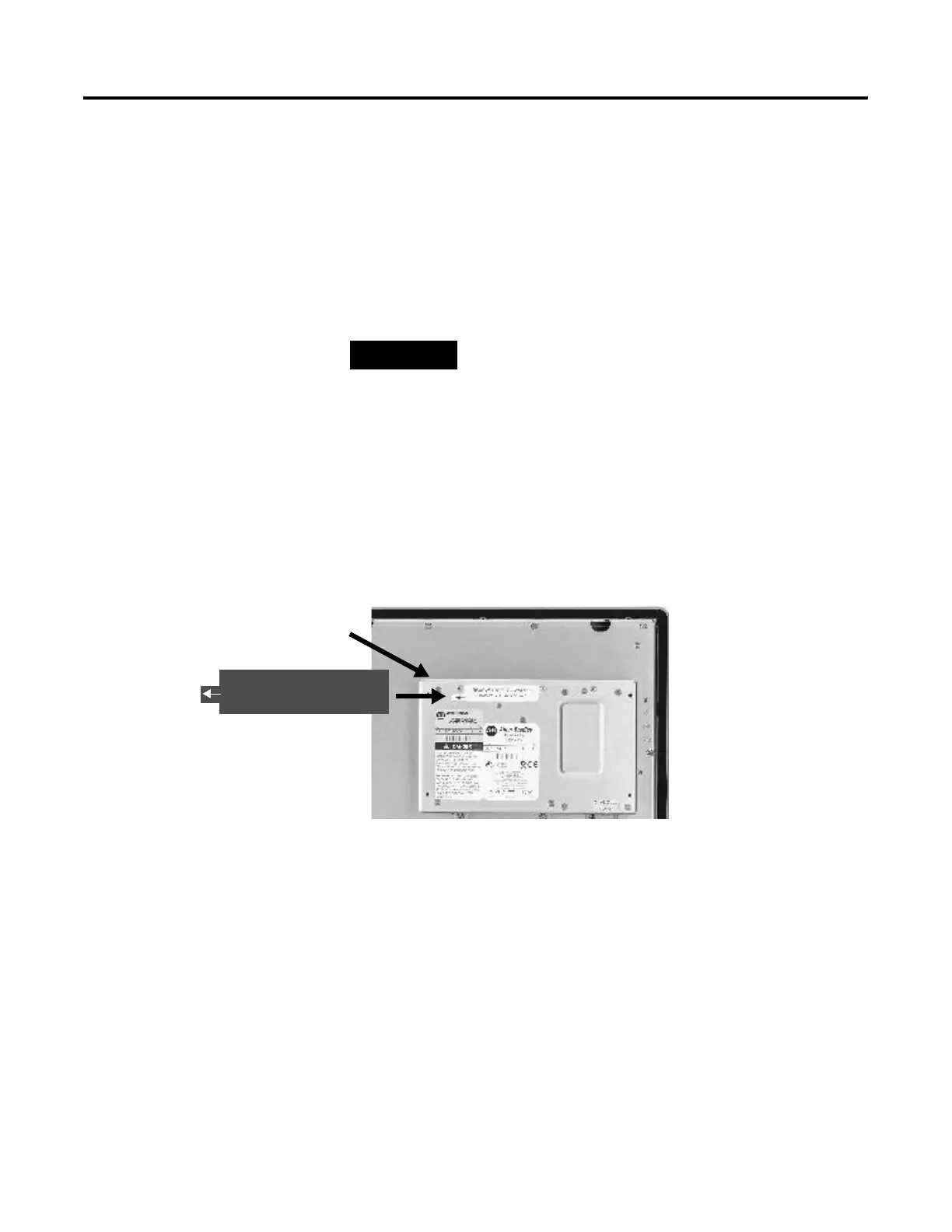
3. Remove the label covering the communication module
connector on the logic module.
4. Position the communication module over the logic module so
that the connectors on bottom of module align with connectors
on the logic module.
TIP
The logic module must be attached to the display
module before you attach the communication
module.
Logic Module
REMOVE LABEL TO INSTALL
COMMUNICATION MODULE

 Loading...


