Publication 2711P-UM001D-EN-P - September 2005
Install and Replace Components 5-7
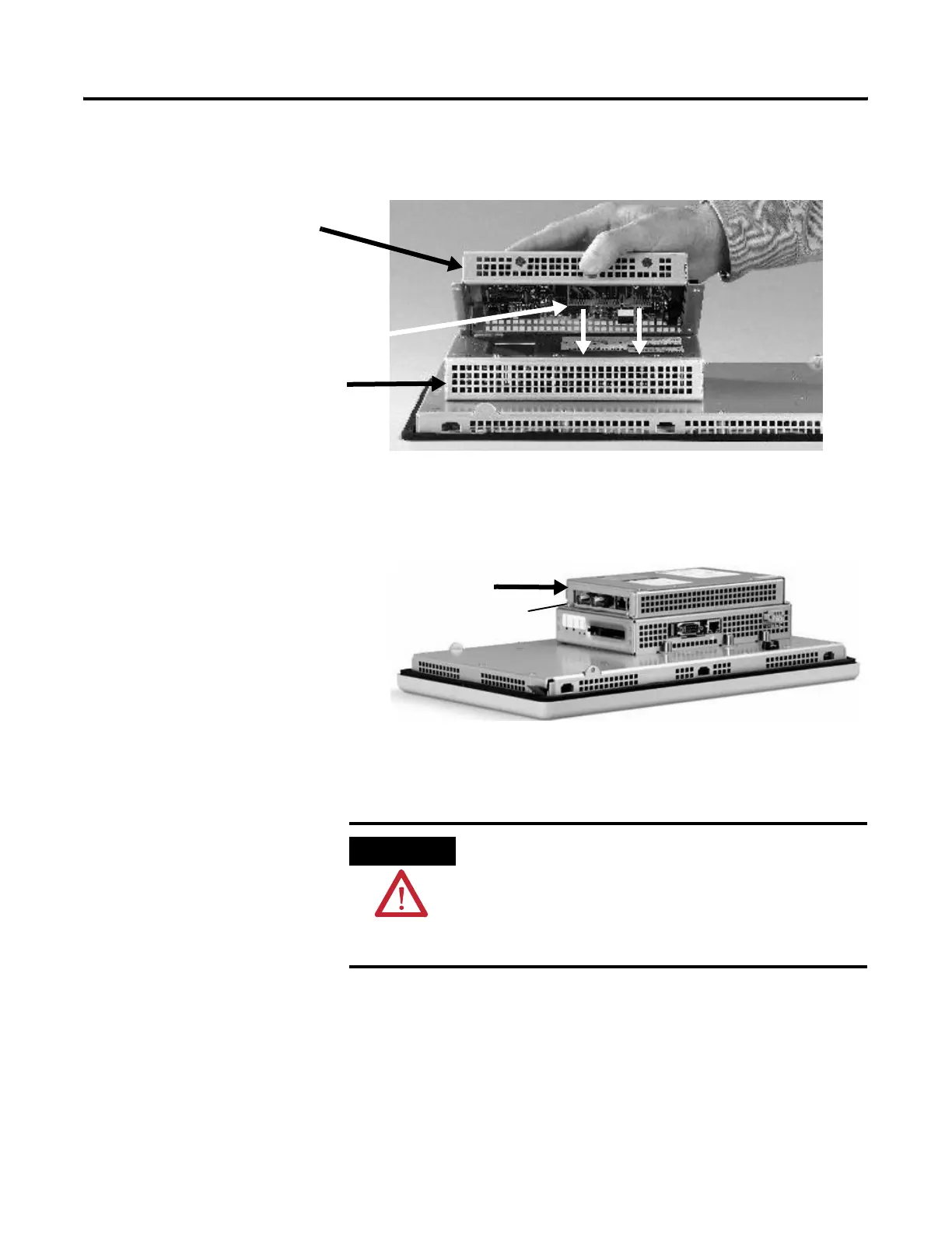
To prevent ESD between the modules, allow the communication
module to touch the logic module before making connection.
5. Push down on the communication module until the connectors
are firmly seated.
6. Tighten the four screws that secure the communication module
to the logic module to a torque of 0.68 Nm (6 to 8 in-lb).
To replace a communication module:
1. Disconnect power from the terminal.
2. Disconnect the communication cables from the module.
3. Remove the four screws that secure the communication module
to the logic module.
4. Carefully lift the communication module away from the logic
module and set aside.
5. Install the new communication module.
Communication
Module
Connector
Logic Module
Screw
Attached
Communication Module
WARNING
Do not connect or disconnect any communication
cable with power applied to this device or any
device on the network. An electrical arc could cause
an explosion in hazardous location installations. Be
sure that power is removed or the area is
nonhazardous before proceeding.

 Loading...


