Publication 2711P-UM001D-EN-P - September 2005
5-8 Install and Replace Components
Install or Replace Communication Module on 400/600 Terminals
To install a communication module:
1. Disconnect power from the terminal.
2. Set the terminal, display side down, on a clean, flat, stable
surface.
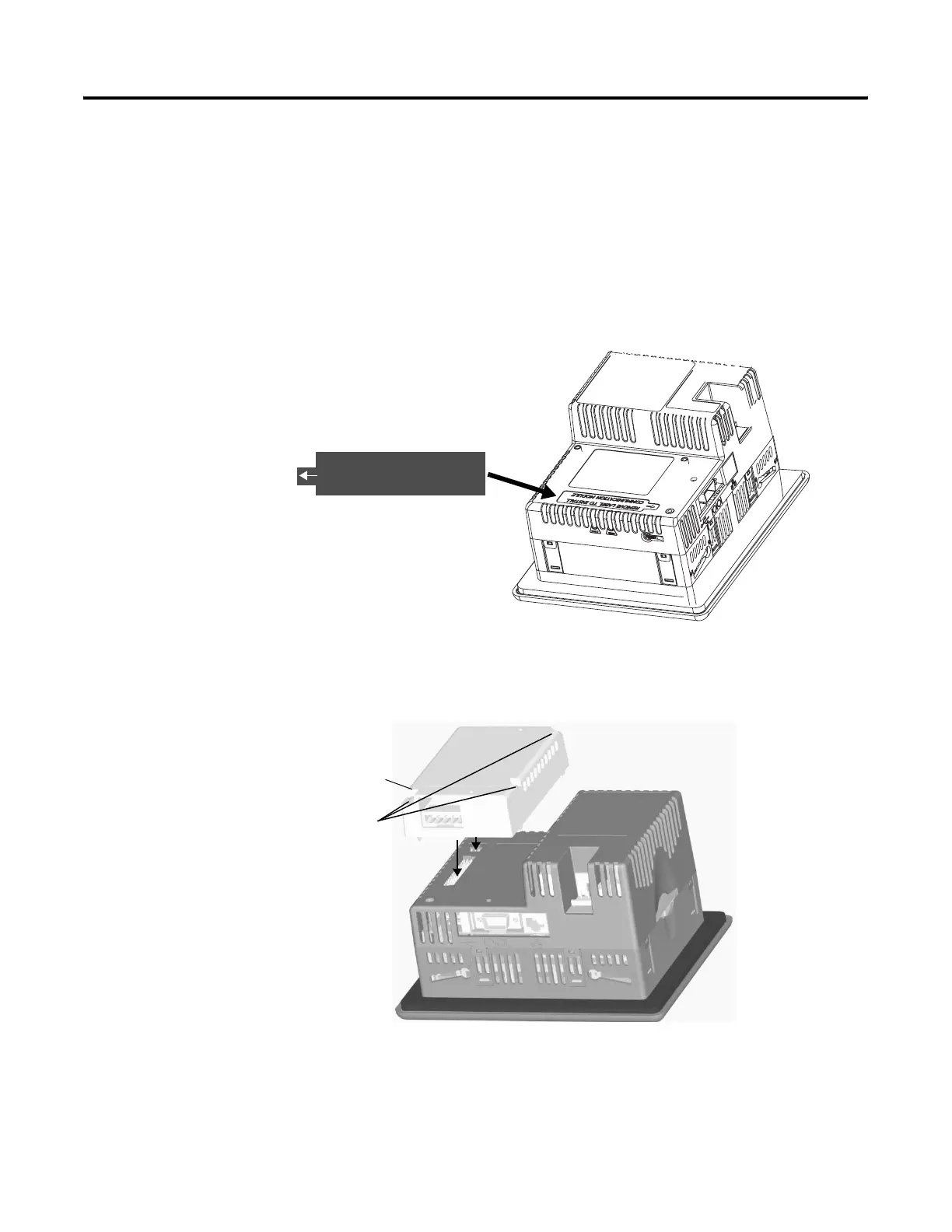
3. Remove the label covering the connectors on the base unit of
the terminal.
4. Position the communication module over back of the terminal
so that the connector on bottom of communication module align
with the connector on the base unit.
5. Push down on the communication module until the connector is
firmly seated.
6. Tighten the three captive screws that secure the module to the
terminal, starting with the bottom, left screw on the module.
Tighten screws to a torque of 0.34 to 0.45 Nm (3 to 4 in-lb).
REMOVE LABEL TO INSTALL
COMMUNICATION MODULE
Captive
Screws
Tighten this
screw first.

 Loading...


