Publication 2711P-UM001D-EN-P - September 2005
5-14 Install and Replace Components
Replace the Bezel
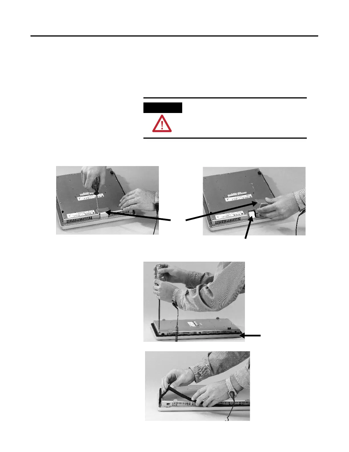
Remove the Display Module Bezel
It is not necessary to remove the logic module or communication
module before removing the bezel, except for the PanelView Plus 700.
1. Disconnect power from the terminal.
2. Set the terminal, display side down, on a flat stable surface.
3. On touch screen only terminals, remove the two screws that
secure the small metal plate to the back of the display module.
4. Disconnect the (touch screen) connector.
5. Remove the screws from the back of the display module. The
number of screws varies for each terminal type.
6. Remove the sealing gasket.
00 - 1500 Terminals Only
ATTENTION
Wear a properly grounded ESD wristband
before touching any of the electronic
components in the logic module.
Plate
Touch Screen Connector
Display Module Bezel

 Loading...


