Publication 2711P-UM001D-EN-P - September 2005
Install and Replace Components 5-13
5. Carefully lift the logic module away from the terminal and flip
over to expose the circuit board.
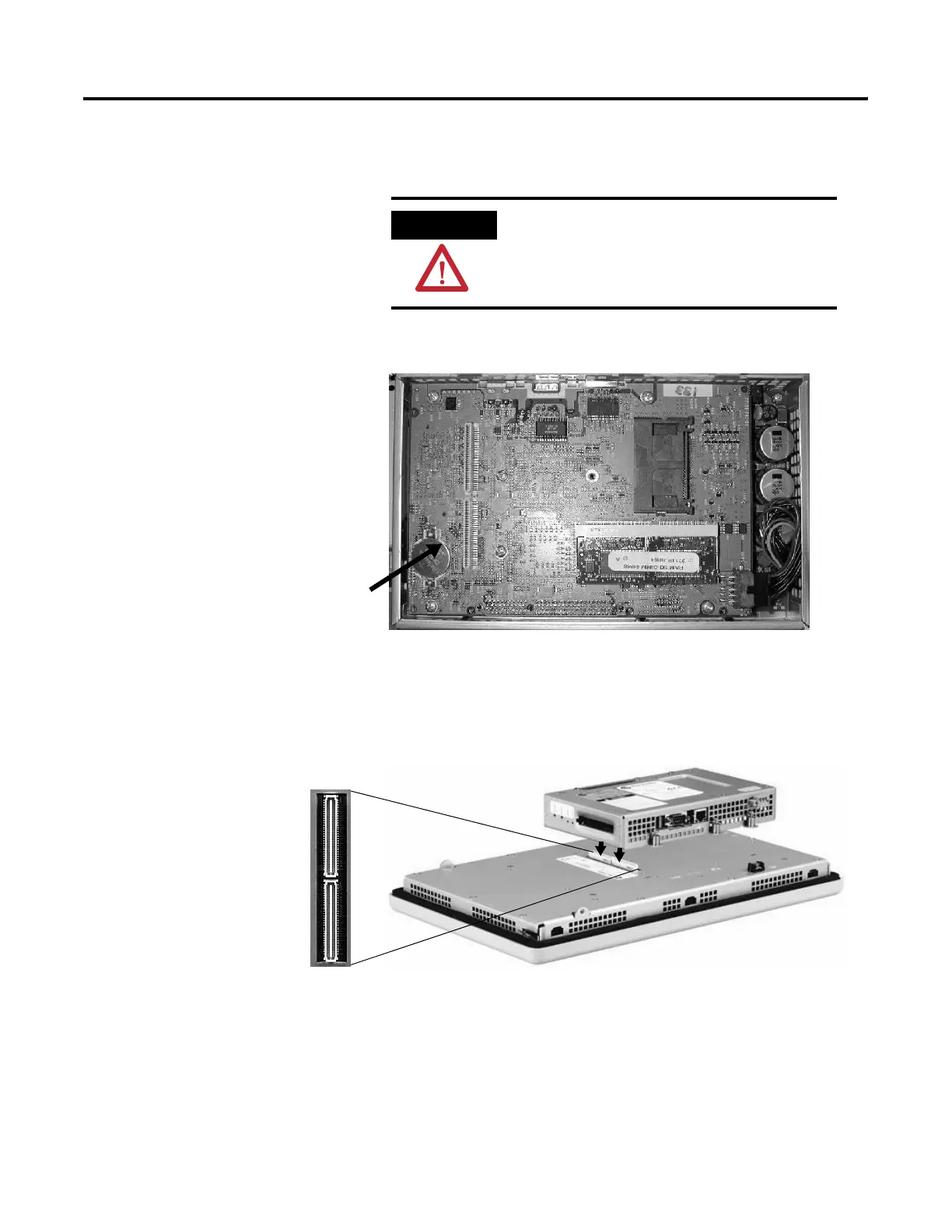
6. Locate the battery on the circuit board.
7. Remove the battery by lifting up the side of the battery.
8. Insert the new battery.
9. Attach the logic module by aligning the two connectors on the
bottom of the module with the connectors on the terminal.
10. Push down on the logic module until firmly seated.
11. Tighten the six captive screws that secure the logic module to a
torque of 0.68 Nm (6 to 8 in-lb).
12. Attach the communication module (if necessary) and tighten the
four screws to a torque of 0.68 Nm (6 to 8 in-lb).
ATTENTION
Wear a properly grounded ESD wristband
before touching any of the electronic
components in the logic module.
Remove battery by lifting up the
edge indicated by arrow.

 Loading...


