Publication 2711P-UM001D-EN-P - September 2005
5-10 Install and Replace Components
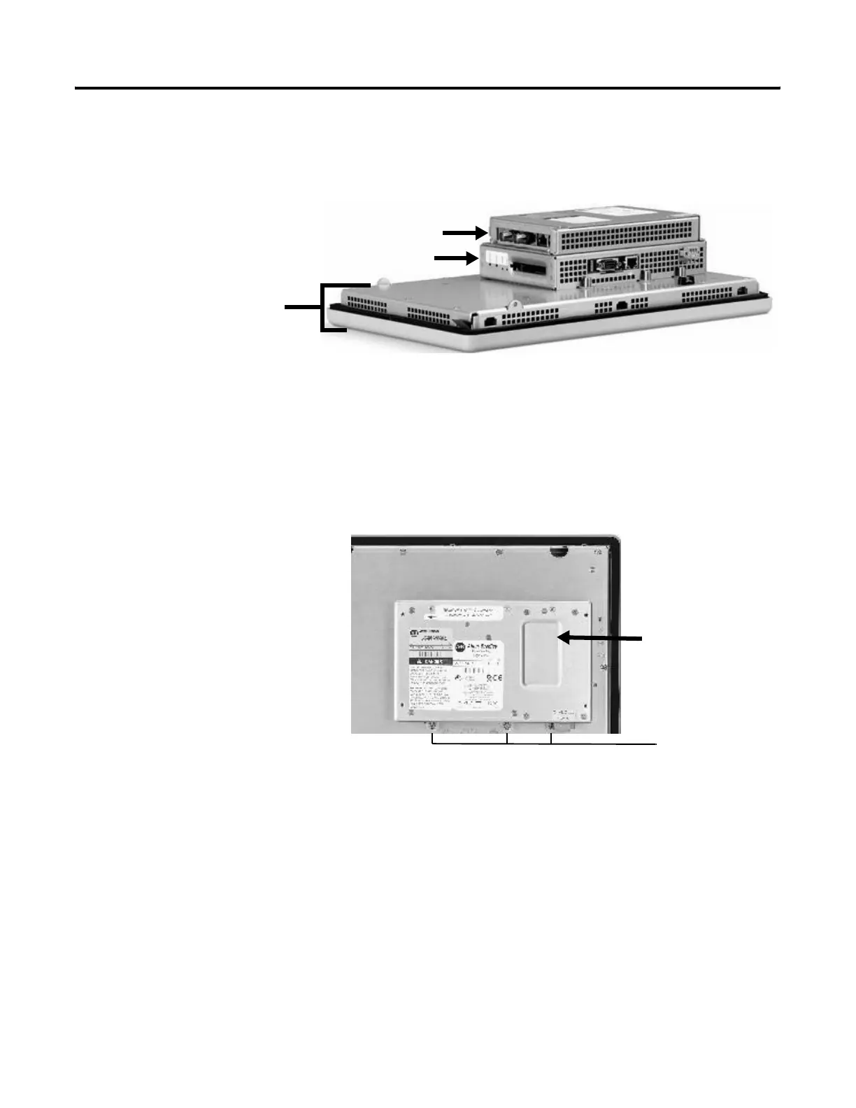
Replace the Display
Module
This section shows how to replace the display module. It is necessary
to remove the communication module from the logic module to
perform this operation.
1. Disconnect power from the terminal.
2. Remove the terminal from the panel.
3. Detach the communication module (if attached) from the logic
module by removing the four screws.
4. Loosen the six captive screws that attach the logic module to the
display module.
5. Carefully lift the logic module from the terminal.
6. Set the display module aside.
700 - 1500 Terminals Only
Communication Module
Display
Module
Logic Module
Logic Module
Captive screws
on top and bottom

 Loading...


