Publication 2711P-UM001D-EN-P - September 2005
Install and Replace Components 5-15
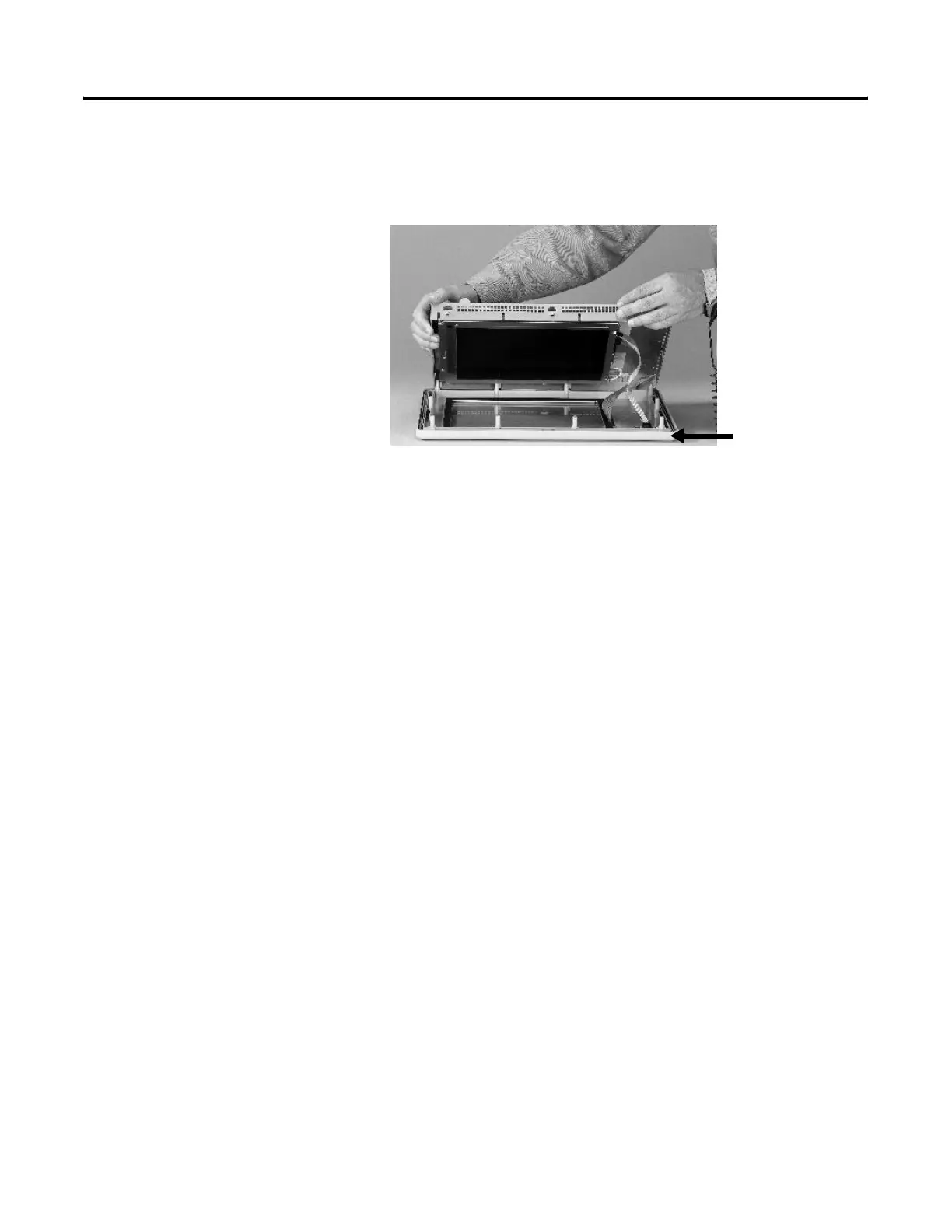
7. Lift the back of the display module away from the bezel.
Work on a clean, flat, stable surface to protect the display from
debris, scratches and damage.
8. Detach all connectors (maximum of three). The number of
connectors varies by model.
• IrDa connector (if present)
• Function key connector
• Touch screen connector
9. Set the bezel aside.
Replace Display Module Bezel
1. Make sure the bezel is free of lint and marks before attaching.
2. Attach the connectors. The number of connectors varies by
model.
• IrDa connector (if present)
• Function key connector
• Touch screen connector
3. Place the back of the display module over the bezel. Be careful
not to pinch any of the cables.
Allow the touch screen connector to extend out of the access
opening.
4. Attach the touch screen connector.
5. Replace the sealing gasket.
6. Attach the screws that secure the display module to the bezel
and tighten to a torque of 1.35 to 1.58 Nm (12 to 14 in-lb).
7. On touch screen terminals, reattach the small metal plate to the
back of the display module using two screws and torque to
0.68 Nm (6 to 8 in-lb).
Display Module Bezel

 Loading...


