EasyManuals Logo
Home>Rockwell Automation>Touch terminals>Allen-Bradley PanelView Plus Series

Rockwell Automation Allen-Bradley PanelView Plus Series User Manual

Rockwell Automation Allen-Bradley PanelView Plus Series
193 pages
To Next Page IconTo Next Page
To Previous Page IconTo Previous Page
Page #130 background imageLoading...
Page #130 background image
Publication 2711P-UM001D-EN-P - September 2005
6-8 Terminal Connections
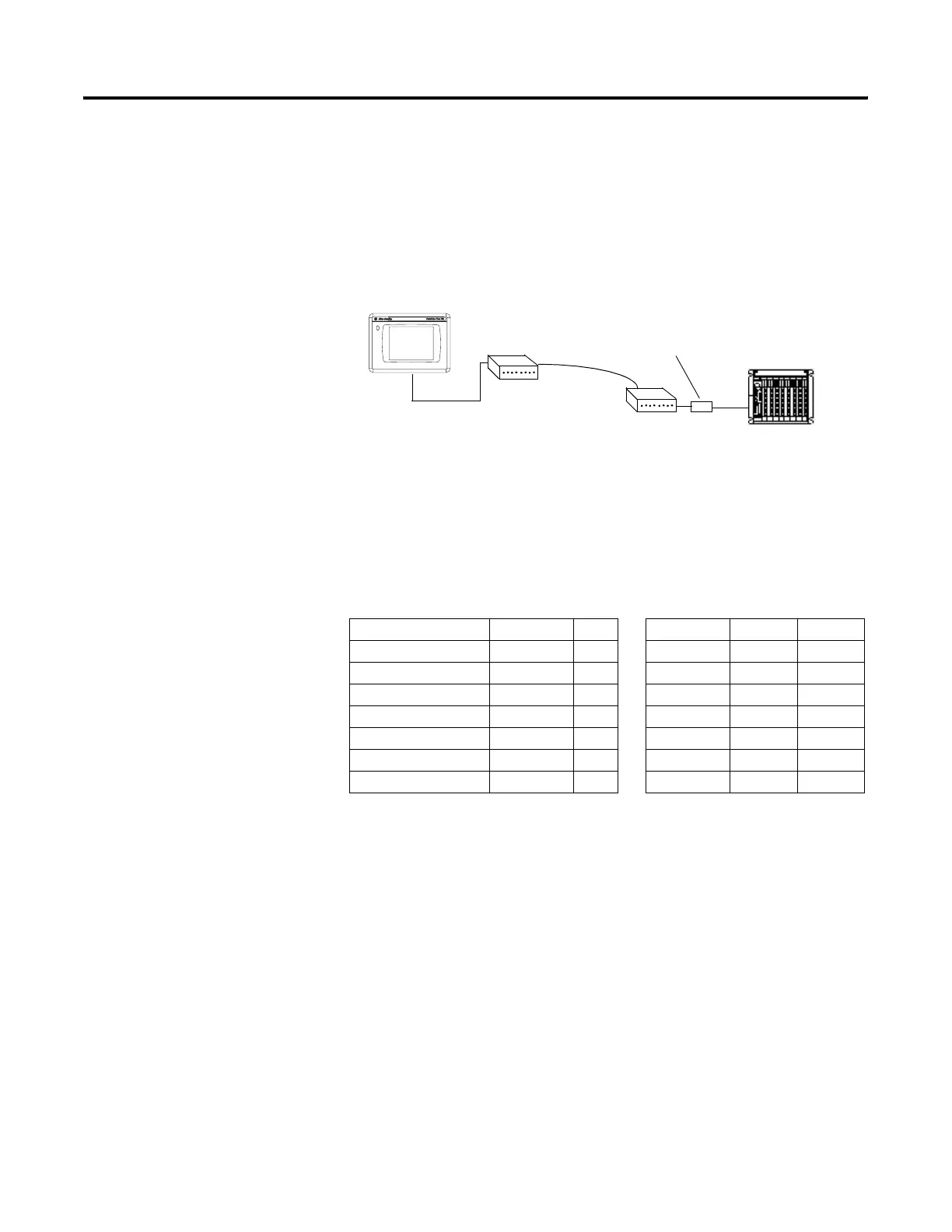
Modem Connection
Wire or radio modem communications is possible between the
terminal and controller. Each modem must support full duplex
communications. Refer to your modem user manual for details on
settings and configuration.
Constructing a Null Modem Cable
To construct a null modem cable, refer to this pinout.
PanelView Plus
9-pin
9-pin PanelView Plus
9-pin
25-pin
FG (Frame Ground) - - - 1 FG
TD (Transmit Data) 3 2 3 3 RD
RD (Receive Data) 2 3 2 2 TD
RTS (Request to Send) 7 8 7 5 CTS
CTS (Clear to Send) 8 7 8 4 RTS
SG (Signal Ground) 5 5 5 7 SG
DSR (Data Set Ready) 6 4 6 20 DTR
DTR (Data Terminal Ready) 4 6 4 6 DSR
DF1 Port
Optical Isolator
Modem
Modem
Controller
PanelView Plus

Table of Contents

Questions and Answers:

Question and Answer IconNeed help?

Do you have a question about the Rockwell Automation Allen-Bradley PanelView Plus Series and is the answer not in the manual?

Rockwell Automation Allen-Bradley PanelView Plus Series Specifications

General IconGeneral
BrandRockwell Automation
ModelAllen-Bradley PanelView Plus Series
CategoryTouch terminals
LanguageEnglish

Related product manuals