Rockwell Automation Publication PFLEX-AP005A-EN-P - October 2010 49
Drive Selection Considerations Chapter 1
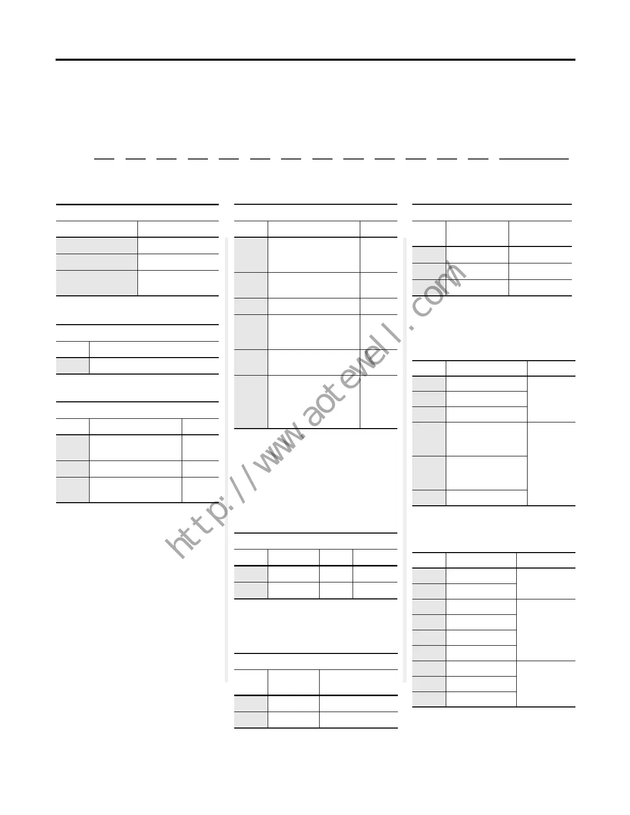
Table 26 - PowerFlex 750-Series Drive Catalog Number Explanation
Position
1 - 3
a
20F
4
b
1
5
c
1
6
d
N
7
e
D
8 - 10
f
248
11
g
A
12
h
A
13
i
0
14
j
N
15
k
N
16
l
N
17
m
N
18
n
N
21G Cabinet Options
- LD - P3 - P11...
a
Drive
Code Type
20F PowerFlex 753
20G PowerFlex 755
21G PowerFlex 755
w/cabinet options
e
Voltage Rating
Code Voltage Phase Prechrg.
C400V AC 3 —
D480V AC 3 —
b
For Future Use
Code Type
1None
c
For Frames 5 and larger, code 4 is required for DC
common bus with precharge.
The optional DC busbar kit (20-750-DCBB1-Fx) is
available for Frames 6 and 7 AC input drives
requiring DC bus terminals.
Input Type
(1)
(1) For Frames 2…4, code 1 also provides the
functionality of DC common bus with precharge.
Code Description Frames
1 AC & DC input
w/precharge
2…5
4 DC input w/precharge 5…7
A AC input w/precharge,
no DC terminals
6…8
d
Enclosure
Code Description Frames
B IP20, NEMA/UL Type 1,
2500 MCC cabinet,
600 mm (23.6 in.) deep
8
F
(1)
(1) For Frame 6 and Frame 7 drives, a user-installed
flange kit is available to convert a code N drive
that provides a NEMA/UL Type 4X back.
Flange, NEMA/UL
Type 4X/12 back
2…5
G IP54, NEMA/UL Type 12 2…7
L IP20, NEMA/UL Type 1,
2500 MCC cabinet,
800 mm (31.5 in.) deep
8
N
(2)
(2) Frames 2…5 drives are IP20; Frame 6 and Frame 7
drives are IP00.
IP20/IP100, NEMA/UL
Type Open
P
(3)
(3) Available as 21G, a drive with cabinet options.
MCC power bus is not UL listed.
IP20, NEMA/UL Type 1,
2500 MCC cabinet and
optional bay w/MCC
power bus, 800 mm
(31.5 in.) deep
8
NOTE: Positions f1 and f2 are on the next page.
g
Filtering and CM Cap Configuration
Code Filtering
Default CM Cap
Connection
A
(1)
(1) Jumpers are included for field configuration as
desired.
Yes Jumper removed
J
(1)
Yes Jumper installed
h
Dynamic Braking
Code
Internal
Resistor
(1)
(1) Available only for Frame 2 drive.
Internal
Transistor
(2)
(2) Standard on Frame 2…5 drives, optional on
Frame 6…7 drives.
ANo Yes
BYes Yes
N No No
21G Cabinet Options (required)
Code Option Type
LD Light duty
System
overload
duty cycle
(1)
(1) Only one option of this type may be selected.
ND Normal duty
HD Heavy duty
P3 Input thermal-
magnetic circuit
breaker
Power
disconnect
or wiring
only bay
(1)
P5 Input non-fused,
molded case
disconnect switch
P14 Wiring only bay
21G Cabinet Options (additional)
Code Option Type
P11 Input contactor
Contactors
(1)(2)
(1) Only one option of this type may be selected.
(2) Contactor options are not available for systems
with MCC power bus.
P12 Output contactor
L1 3% input reactor
Reactors
(1)
L2 3% output reactor
L3 5% input reactor
L4 5% output reactor
P20 1250 amp bus
MCC power
bus capacity
(1)
P22 2000 amp bus
P24 3200 amp bus

 Loading...


