110 Rockwell Automation Publication 750-PM101B-EN-P - April 2022
Chapter 4 Troubleshooting
22 VbusErr
The instantane
ous error signal between the DC Bus
command and the measured DC bus. This signal is
processed through the controller of the bus
regulator to generate the current reference
command.
REAL Volts
23 VbusRegKi The integral gain of the bus voltage regulator. REAL AS/V
24 VbusRegKp The proportional gain of the bus voltage regulator. REAL A/V
25 IqRefVbusReg
The instantaneous value of the active current
command generated by the DC bus voltage
regulator.
REAL A
26 IqRefComp
The instantaneous value of the active current (q-
axis current component in the synchronous
reference frame) calculated by the LCL steady state
compensation algorithm.
REAL A
27 VqRefComp
The instantaneous value of the grid line voltage (q-
axis voltage component in the synchronous
reference frame) calculated by the LCL steady state
compensation algorithm.
REAL Volts
28 VdRefComp
The instantaneous value of the grid line voltage (d-
axis voltage component in the synchronous
reference frame) calculated by the LCL steady state
compensation algorithm.
REAL Volts
29 IdRefComp
The instantaneous value of the reactive current (d-
axis current component in the synchronous
reference frame) calculated by the LCL steady state
compensation algorithm.
REAL A
30 IqVbusCurLim
The maximum value of the active current
component for a given DC bus value, line voltage
magnitude, and line reactance, this limit is
calculated based on the maximum active power
transfer theoretically achievable between the AFE
converter and the grid.
REAL A
31 IdVbusCurLim
The maximum value of the reactive current
component for a given DC bus value, line voltage
magnitude, and line reactance, this limit is
calculated based on the maximum reactive power
transfer theoretically achievable between the AFE
converter and the grid.
REAL A
32 ILmtUserSts
A status signal that indicates current is limited by
the user current limit parameter.
DINT t/f
33 IdRefSts A status signal that indicates d-axis current at limit. DINT t/f
34 IqSyncErr
The instantaneous error signal between the active
current command and the calculated active current.
This signal is processed through the controller of
the current regulator to generate the reference
voltage command.
REAL A
35 IdSyncErr
The instantaneous error signal between the reactive
current command and the calculated reactive
current component. This signal is processed
through the controller of the current regulator to
generate the reference voltage command.
REAL A
36 CurRegKiIq
The integral gain of the current regulator of the
active current component.
REAL VSec/A
37 CurRegKpIq
The proportional gain of the current regulator of the
active current component.
REAL V/A
38 CurRegKiId
The integral gain of the current regulator of the
reactive current component.
REAL VSec/A
39 CurRegKpId
The proportional gain of the current regulator of the
reactive current component.
REAL V/A
40 CurRegqOut
The output signal of the current regulator used to
regulate the active current component which
includes the effect of both the proportional action
and the integral action.
REAL Volts
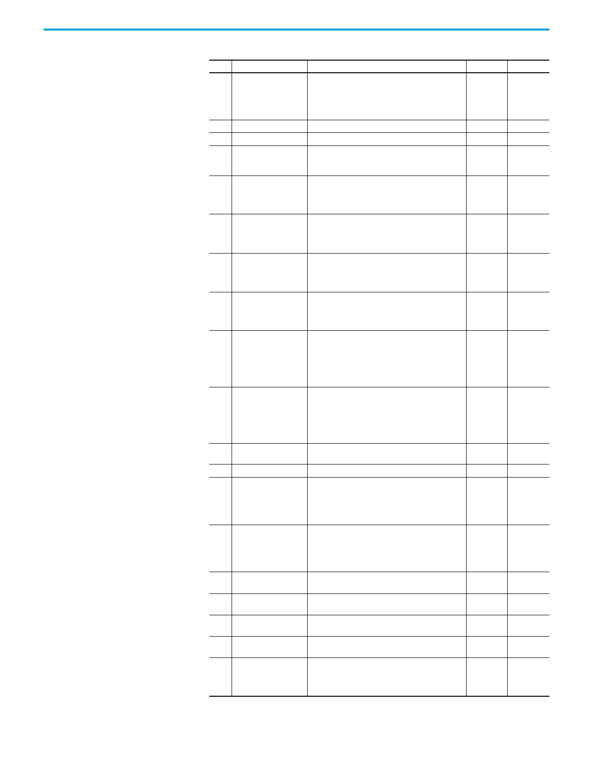
Port 13 Testpoint Codes (Continued)
No. Display Name Description Data Type Units

 Loading...


