Chapter Installation and Wiring
2-8
2
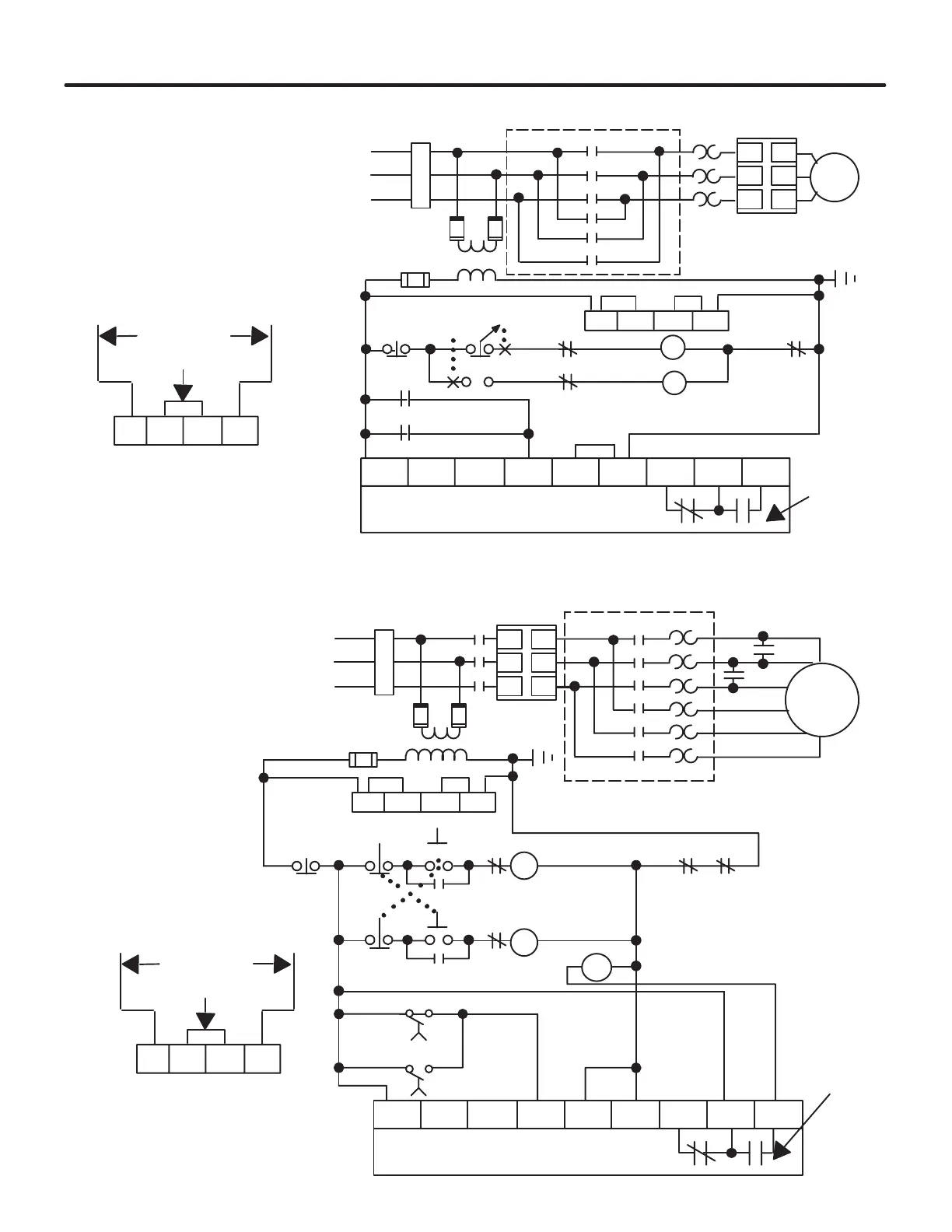
Figure 2.14 - Typical Application with a Single Speed, Reversing Starter
M
L1/1
L2/3
L3/5
T1/2
T2/4
T3/6
11 12 13 14
R
10 20 30 40 50 60 70 80 90
F
11 12 13 14
SMC PLUS Control Terminals
Optional
220/240 VAC Fan Power
Jumper
To Supply
SMC PLUS
Controller
Fan Power
(97A and
135A Only)
Auxiliary
Contacts
Power Input
3-Phase
O.L. ➀
➀
➀
Branch
Protection
➀
R
➀
➀
➀
F
➀
R
➀
Stop ➀
For
Off
Rev
➀
R
➀
F
➀
➀ Customer Supplied
NOTE: Minimum transition time for
reversing direction is 1/2 second.
Reversing Motor Starter
Figure 2.15 - Typical Application with a Two-Speed Motor Starter
M
L1/1
L2/3
L3/5
T1/2
T2/4
T3/6
11 12 13 14
10 20 30 40 50 60 70 80 90
1 sec.
1 sec.
11 12 13 14
SMC PLUS Control Terminals
Optional
220/240 VAC Fan Power
Jumper
To Supply
SMC PLUS
Controller
Fan Power
(97A and
135A Only)
Auxiliary
Contacts
➁
Power Input
3-Phase
➀
Branch
Protection
➀
➀
Stop ➀
➀
IC ➀
Two-Speed Motor Starter ➀
Low
LOL
High HOL
High ➀
Low ➀
H
L
L
L
H
H
IC
➀
➀
HOL ➀LOL ➀
L
H
➀
➀
➀ Customer Supplied
➁ Set auxiliary contacts for normal setting.
 Loading...


