Chapter Installation and Wiring
2-4
2
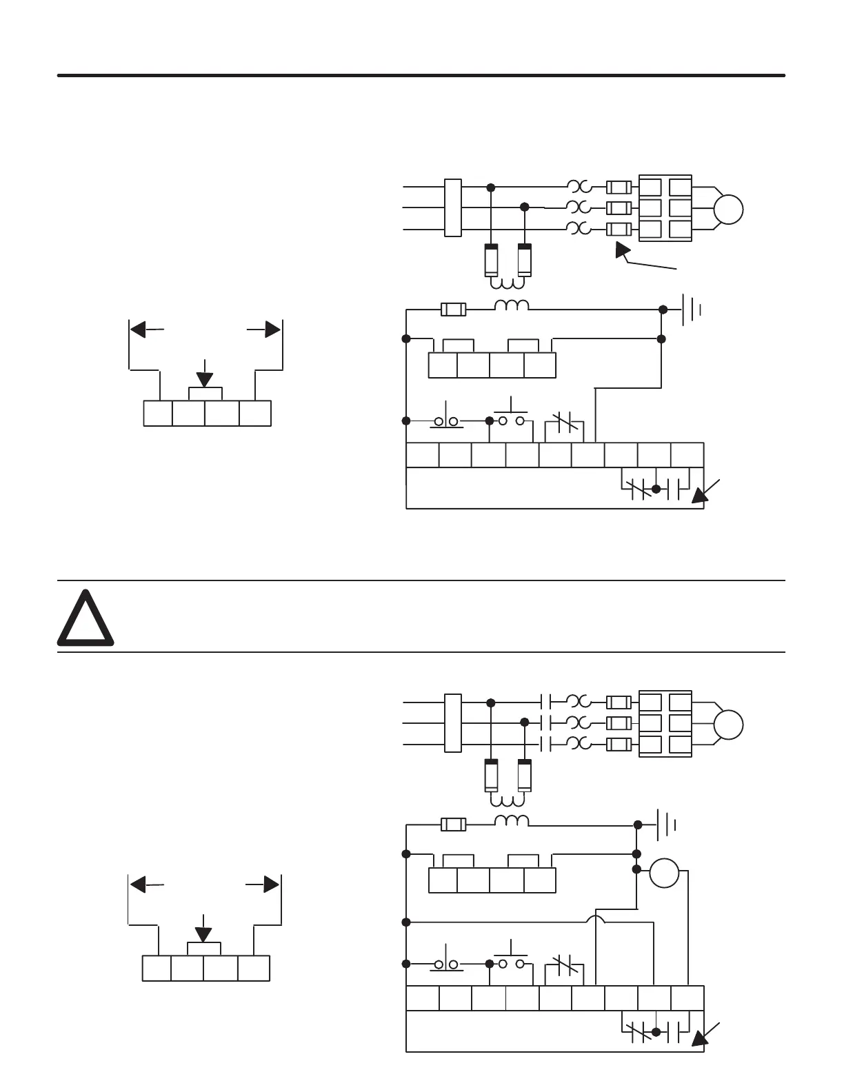
Figure 2.7 shows a typical connection for standard control module. See page 3-2
for a description of the start sequence.
Figure 2.7 - Typical Connection Diagram for Standard Unit
10 20 30 40 50 60 70 80 90
Stop
Start
M
L1/1
L2/3
L3/5
T1/2
T2/4
T3/6
SMC PLUS
Controller
Overload
Relay ➀
Fast-Acting
SCR fuses
(optional) ➀
SMC PLUS Control Terminals
11 12 13 14
Fan Power
(97A and
135A Only) ➁
O.L.
Auxiliary
Contacts
11 12 13 14
Optional
220/240 VAC Fan Power
Jumper
Branch
Protection
➀
Jumper
To Supply
Power Input
3-Phase
➀
➀
➀
➀
➀
➀
➀
➀ Customer Supplied
➁ Customer wires fan to control voltage supply.
Jumpers are arranged for 110/120 VAC fan power.
NOTE: For two wire control, remove stop/start
push buttons and connect two wire device
between terminals 10 and 40.
Figure 2.8 shows a typical connection of standard unit for use with an isolation
contactor. Starting and stopping of the motor is controlled by the controller. The
controller also controls the electromechanical contactor. The contactor provides
isolation between the motor and the power lines when the controller is “OFF.”
WARNING: When not using an isolation contactor, hazardous voltages are present at the load terminals
of the controller when the controller is turned off. Warning labels must be attached to the motor
terminal box, the controller enclosure, and the control station. Additional circuitry must be included to
provide automatic isolation.
!
Figure 2.8 - Typical Connection Diagram of Standard Unit with Isolation Contactor
10 20 30 40 50 60 70 80 90
M
L1/1
L2/3
L3/5
T1/2
T2/4
T3/6
11 12 13 14
11 12 13 14
C.I.
Stop
Start
SMC PLUS
Controller
Fast-Acting
SCR fuses
(optional) ➀
SMC PLUS Control Terminals
Fan Power
(97A and
135A Only) ➁
O.L.
Auxiliary
Contacts
➂
Optional
220/240 VAC Fan Power
Jumper
Branch
Protection
➀
Jumper
To Supply
Power Input
3-Phase
➀
➀
➀
➀
➀
➀
➀
➀ Customer Supplied
➁ Customer wires fan to control voltage supply.
Jumpers are arranged for 110/120 VAC fan power.
➂ Set auxiliary contact for normal setting.
NOTE: For two wire control, remove stop/start
push buttons and connect two wire device
between terminals 10 and 40.
Typical Connection
Typical Connection
with Isolation
Contactor
 Loading...


