Chapter Installation & Wiring
2
2-5
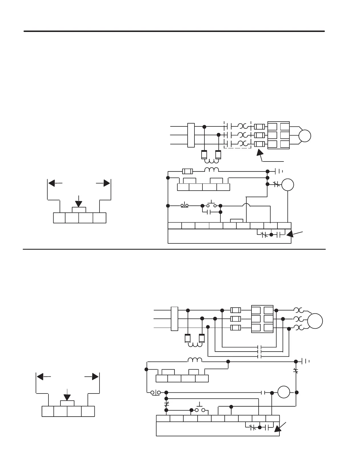
Figure 2.9 shows a typical connection diagram for use in a retrofit application. In
this scheme, the controller provides control of the load when the electromechanical
starter is energized. This method of controlling the load can be used in applications
where the existing control scheme is to remain intact.
Starting and stopping of the motor is controlled by the controller. The controller
also controls the electromechanical contactor. The contactor provides isolation
between the motor and the power lines when the controller is “OFF.”
If a fault occurs, the N.O. auxiliary contact opens and drops out the “M” contactor,
thus providing isolation from line potential. In this scheme the auxiliary contact
selection DIP switch must be set for normal auxiliary contact operations.
Figure 2.9 - Typical Connection Diagram for Retrofit Applications of
Standard Unit
➀
Stop
Start
SMC PLUS
Controller
Fast-Acting
SCR fuses
(optional) ➀
SMC PLUS Control Terminals
Fan Power
(97A and
135A Only) ➁
O.L.
Auxiliary
Contacts
➂
Optional
220/240 VAC Fan Power
Jumper
Branch
Protection
➀
Jumper
To Supply
Power Input
3-Phase
➀
➀
➀
➀
➀
➀
10 20 30 40 50 60 70 80 90
L1/1
L2/3
L3/5
T1/2
T2/4
T3/6
11 12 13 14
M
Existing Motor
Starter ➀
M
M
M
11 12 13 14
➀
➀ Customer Supplied
➁ Customer wires fan to control voltage supply.
Jumpers are arranged for 110/120 VAC fan power.
➂ Set auxiliary contact for normal setting.
NOTE: For two wire control, remove stop/start
push buttons and connect two wire device
between terminals 10 and 40.
By using the controller as shown in Figure 2.10 below, a soft start characteristic can
be provided. Once the motor has reached full speed, the auxiliary contact on the
SMC energizes the bypass contactor.
NOTE:
The controller is by-passed in this circuit. Controller features are not
available once the by-pass contactor is energized. Also, auxiliary contacts
must be set for up to speed operation.
Figure 2.10 - Typical Application Diagram of a By-Pass Contactor with Standard Unit
M
L1/1
L2/3
L3/5
T1/2
T2/4
T3/6
11 12 13 14
10 20 30 40 50 60 70 80 90
BC
11 12 13 14
Stop ➀
Start ➀
SMC PLUS
Controller
Fast-Acting
SCR fuses
(optional)
➀
SMC PLUS Control Terminals
Fan Power
(97A and
135A Only) ➁
Auxiliary
Contacts
➂
Optional
220/240 VAC Fan Power
Branch
Protection
➀
Jumper
To Supply
Power Input
3-Phase
➀
➀
➀
BC
BC
➀
O.L.
➀
Bypass
Contactor
➀ Customer Supplied
➁ Customer wires fan to control voltage supply.
Jumpers are arranged for 110/120 VAC fan power.
➂ Set auxiliary contacts for up-to-speed setting.
NOTE: For two wire control, remove stop/start
push buttons and connect two wire device
between terminals 10 and 40.
BC
L.B.
Typical Connection
for Retrofit
Application
By-Pass Mode
 Loading...


