Chapter Troubleshooting
4-6
4
7. Measure resistance between pins 2 and 3. Resistance should be less than 100
ohms.
8. Measure resistance between pins 6 and 7. Resistance should be less than 100
ohms.
9. Measure resistance between pins 4 and 5. Resistance should be less than 250
ohms.
If the power module fails for any of the above tests, replace it.
The gold interconnection pins on the power module are protected with a special
contact lubricant. Do not clean or wipe these pins. This contact lubricant is
necessary for proper operation. Inspect each pin prior to assembly of the control
module. If the lubricant is missing, apply a thin film of the recommended contact
lubricant.
The Allen-Bradley approved contact lubricant is NYOGEL 759G, manufactured by
William F. Nye, Inc., Specialty Lubricants, New Bedford, MA 02742 U.S.A.
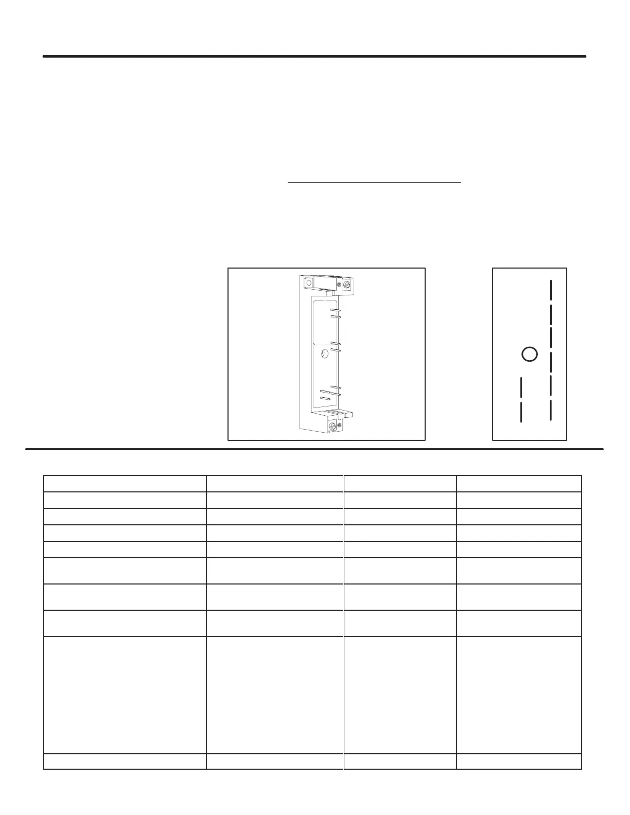
Figure 4.6 - Pin Locations for Power Module Resistance Check
2
3
7
6
1
4
8
5
Renewal Parts
Description Controller Rating Line Voltage Rating Part Number
Control Module (Standard) All All 40888-899-01
Preset Slow Speed All All 40888-899-03
Soft Stop All All 40888-899-02
Pump Control All All 40888-899-14
SMB
Smart Motor Braking
24A-54A
97A-135A
All
40888-899-09
40888-899-10
Accu-Stop
24A-54A
97A-135A
All
40888-899-04
40888-899-05
Slow Speed with Braking
24A-54A
97A-135A
All
40888-899-15
40888-899-16
Power
Modules
24A
35A
54A
97A
135A
200-480
200-600
200-480
200-600
200-480
200-600
200-480
200-600
200-480
200-600
40382-899-02
40382-899-04
40382-899-03
40382-899-04
40382-899-03
40382-899-04
40382-806-01
40382-806-02
40382-806-03
40382-806-04
Fan 97A-135A All 40382-807-01
Power Module
Resistance Check
(continued)
 Loading...


