Chapter Set-up Procedures: SMP PLUS
Controller without Options
3-2
3
The line fault indicates an abnormal condition has been sensed in the line.
Conditions which will cause line fault indications are phase loss, open motor lead
and shorted SCR.
If detected in either the “Starting” or “Running” modes, the controller trips and the
FAULT and LINE LEDs light.
The controller has been factory-set for the following as shown in Figure 3.3:
• 10 second soft start
• Energy Saver “OFF”
• Auxiliary Contacts “OFF” (Normal)
• Stall feature “OFF”
• Initial Torque 70%
• Kickstart “OFF”
When wired as indicated in the typical connection diagram, the controller operates
as follows:
Pressing the Start push button signals the controller to initiate the “Start” sequence,
provided the overload contacts are closed. The STARTING LED turns on, the
internal hold-in circuit latches across terminals 30 and 40, and the Form C auxiliary
contacts simultaneously change state (if so selected on the DIP switches). The
controller then applies voltage to the motor to an initial value. This voltage rise
continues (in the soft start mode) until the motor reaches full voltage or the motor is
up-to-speed. At that point, the RUNNING LED turns on and the STARTING LED
turns off. If “up-to-speed” auxiliary contacts are selected instead of normal
auxiliaries, these auxiliary contacts would change state at this time.
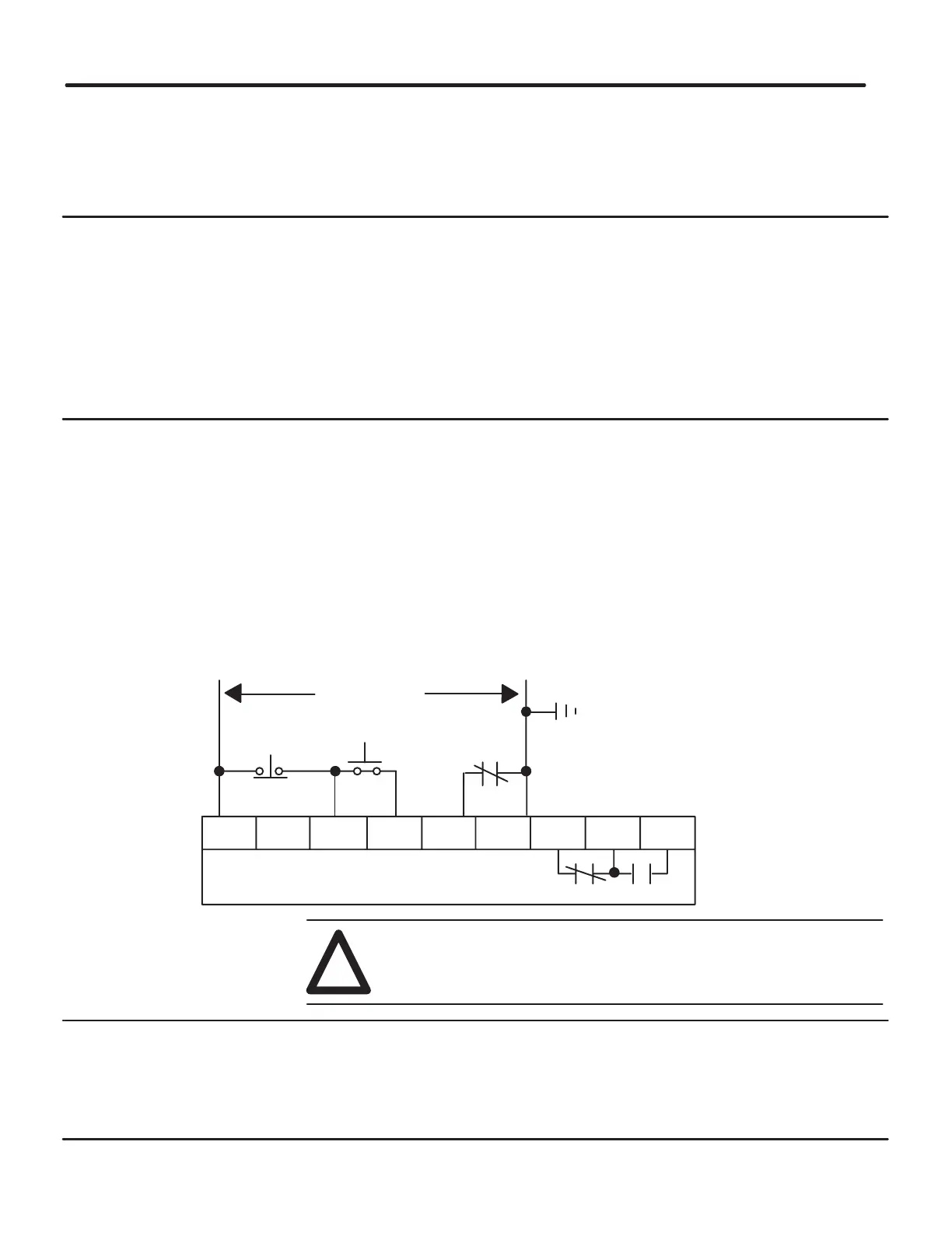
Figure 3.2 - Typical Connection Diagram for Standard Unit
10 20 30 40 50 60 70 80 90
SMC PLUS Control Terminals
Auxiliary Contacts
Control Power
Stop ➀ ➁
Start ➀ ➁
O.L. ➀
➀ Customer Supplied
➁ For two wire control, remove stop/start
push buttons and connect two wire device
between terminals 10 and 40.
WARNING: Disconnect main power before servicing motor controller
or associated wiring. Hazardous voltages are present in the motor
circuit even when the solid-state controller is off.
!
Pressing the Stop push button signals the controller to initiate a shutdown. The
controller stops firing the SCRs allowing the load to stop. When the logic
completes its shutdown sequence, it releases the latch circuit across terminals 30
and 40, and the Form C auxiliary contacts change over. The RUNNING LED turns
off.
When an overload trip occurs the normally closed contact (wired into terminals 50
and 60) opens, causing the controller logic to shut off immediately.
Line Fault
Factory Settings
Start Sequence
Normal Stop
Sequence
Overload Trips
 Loading...


