Chapter Installation and Wiring
2-2
2
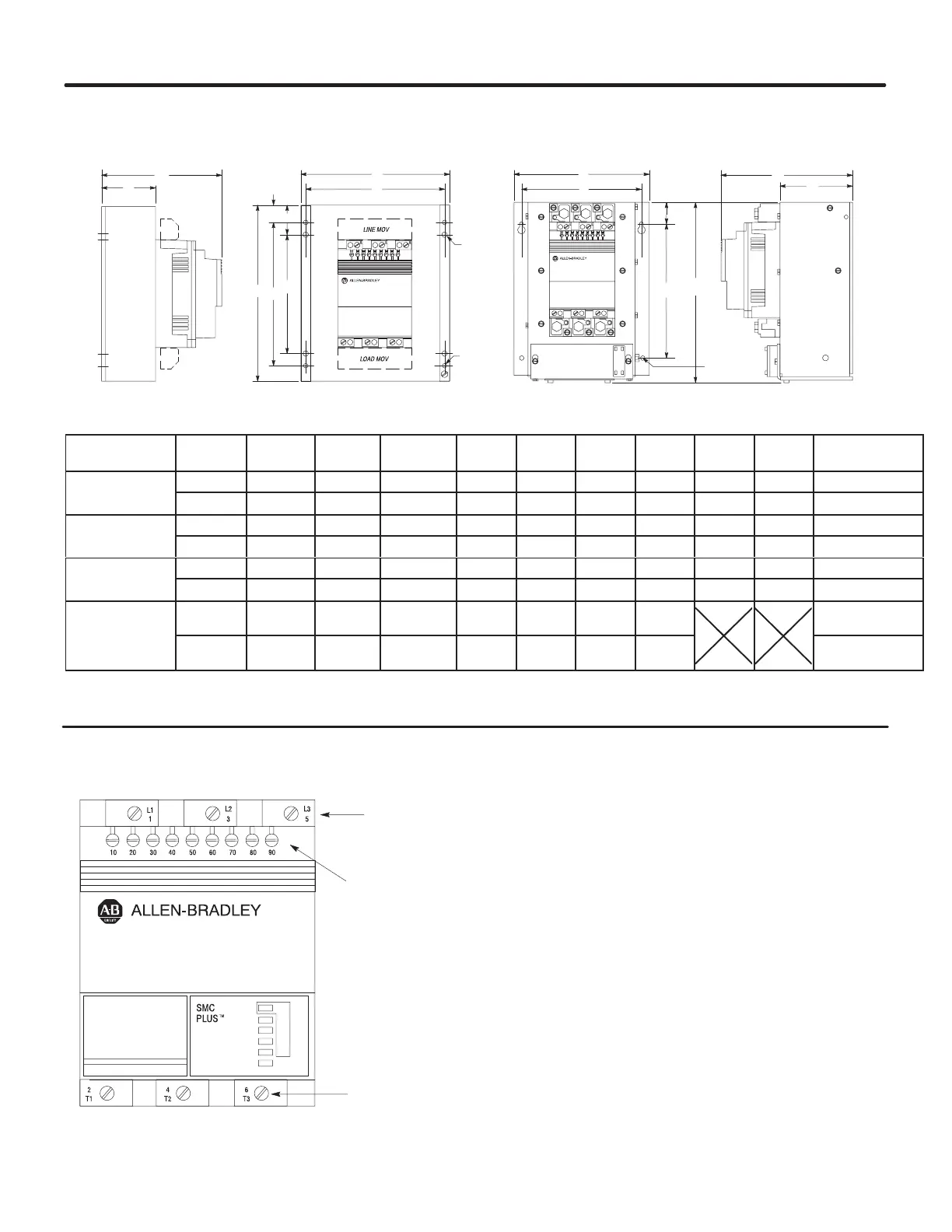
Figure 2.2 - Dimension Drawings
24, 35, and 54 Amp Controller 97 and 135 Amp Controller
AA
C
DE
H
J
B
F
G
E
G
F
B
C
D
.281 DIA.
(04.14)
4 Mtg. Holes
.219 DIA.
(05.56)
4 Mtg. Holes
.281 DIA.
(04.14)
4 Mtg. Holes
Unit
A
Width
B
Height
C
Depth
D E F G H J
Approx.
Ship. Wt.
24A
Millimeter 154 180 159 50 140 160 140 10 20 4.5 kg
Controller
Inch 6-1/16 7-3/32 6-17/64 1-31/32 5-33/64 6-5/16 5-33/64 13/32 51/64 10 lbs
35A
Millimeter 214 240 169 60 200 200 180 20 30 6.8 kg
Controller
Inch 8-7/16 9-29/64 6-21/32 2-23/64 7-7/8 7-7/8 7-3/32 51/64 1-3/16 15 lbs
54A
Millimeter 244 290 199 90 230 240 200 25 45 11.3 kg
Controller
Inch 9-39/64 11-27/64 7-27/32 3-35/64 9-1/64 9-29/64 7-7/8 63/64 1-25/32 25 lbs
97A
and
Millimeter 248 336 230 128 220 250 40
10.4 kg (97A)
11.8 kg (135A)
35A
Controllers
Inch 9-49/64 13-15/64 9-1/16 5-3/64 8-21/32 9-27/32 1-39/64
23 lbs (97A)
26 lbs (135A)
All dimensions are approximate and are not to be used for construction purposes. Refer to nearest Sales Office or the Sales Department at
Milwaukee, Wisconsin, for complete dimension drawings.
Figure 2.3 - Wiring Terminal Locations
The controller wiring terminal locations
are shown in Figure 2.3. Make wiring
connections as indicated in the typical
connection diagrams shown in Figures
2.7, 2.8, 2.9, 2.10, and 2.11. Connect
the line to terminals L1/1, L2/3, and
L3/5. Connect the load to terminals
T1/2, T2/4, and T3/6. A provision is
available for grounding the isolated
heatsink per applicable codes.
Wiring
Input
Connections
Control
Circuit
Connections
Output
Connections
 Loading...


