EasyManuals Logo

Rockwell Automation Allen-Bradley VersaView 5000 User Manual

Rockwell Automation Allen-Bradley VersaView 5000
28 pages
To Next Page IconTo Next Page
To Previous Page IconTo Previous Page
Page #17 background imageLoading...
Page #17 background image
Rockwell Automation Publication 6200-IN001A-EN-P - October 2019 17
VersaView 5000 Thin Clients, Industrial Computers, and Accessories for Hazardous Locations
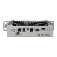
3. Remove the four screws that secure the factory-installed mounting plate to the back of
the VersaView 5000 device.
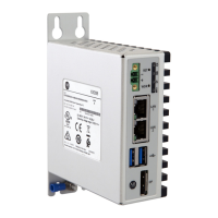
4. Install the new backplate supplied with the VESA mounting bracket kit with the four
screws that you removed in step 3
.
5. Reinstall the two screws that you removed in step 2.
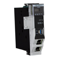
6. With four customer-supplied screws, install the VESA mounting bracket to the VESA
mounting arm.
TIP For this step and step 5
, tighten the reinstalled Torx screws to a torque of 0.5 ft•lb
(0.7 N•m).

Questions and Answers:

Question and Answer IconNeed help?

Do you have a question about the Rockwell Automation Allen-Bradley VersaView 5000 and is the answer not in the manual?

Rockwell Automation Allen-Bradley VersaView 5000 Specifications

General IconGeneral
BrandRockwell Automation
ModelAllen-Bradley VersaView 5000
CategoryIndustrial PC
LanguageEnglish

Related product manuals