Rockwell Automation Publication 520-UM001I-EN-E - July 2016 221
Encoder/Pulse Train Usage and Position StepLogic Application Appendix E
In all position modes, the following parameters will control the characteristics at
each step:
L200
, L202, L204, L206, L208, L210, L212 and L214 [Step Units x] are the
number value to the left of the decimal (whole number) of the 8 positions desired
for an application, beginning with Step 0 (L200) and continuing with each step
until Step 7 (L214). For example, enter 2 into this parameter if you would like a
commanded position of 2.77.
L201, L203, L205, L207, L209, L211, L213 and L215 [Step Units F x] are the
number value to the right of the decimal (the portion less than 1) of the 8
positions desired for an application, beginning with Step 0 (L201) and
continuing with each step until Step 7 (L215). For example, enter 0.77 into this
parameter if you would like a commanded position of 2.77.
A410
...A417 [Preset Freq x] are the parameters that define the maximum
frequency the drive will run at during the corresponding step. For example, if
[Preset Freq 2] is set to 40 Hz, the drive will accelerate to 40 Hz maximum when
moving to Position 2.
L190
...L197 [Stp Logic Time x] are the parameters that define the time the drive
will remain in each corresponding step if that step is time-based. For example, if
L192
[Stp Logic Time 2] is set to 5.0 seconds and that step is time-based, the
drive will remain in Step 2 for 5.0 seconds. Note that this is the total time in that
step, not the time at that position. Therefore, it will include the time needed to
accelerate, run, and decelerate to that position.
L180
...L187 [Stp Logic x] are the parameters that allow additional flexibility and
control various aspects of each step when a positioning mode is selected that
utilizes the Step Logic functions. Note that in Positioning mode these parameters
have a different function than when used for normal velocity Step Logic. Each of
the 4 digits controls one aspect of the each position step. The following is a listing
of the available settings for each digit:
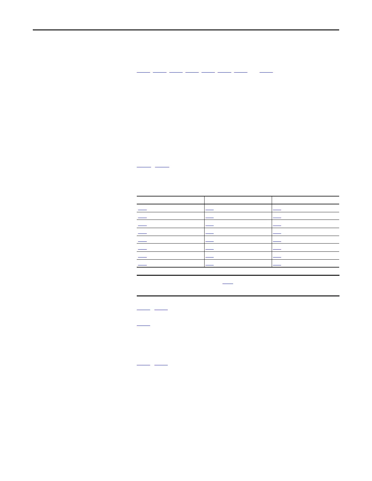
Frequency Source Step Source Position Source
A410
[Preset Freq 0] L180 [Stp Logic 0] L200 [Step Units 0]
A411
[Preset Freq 1] L181 [Stp Logic 1] L202 [Step Units 1]
A412 [Preset Freq 2] L182 [Stp Logic 2] L204 [Step Units 2]
A413
[Preset Freq 3] L183 [Stp Logic 3] L206 [Step Units 3]
A414
[Preset Freq 4] L184 [Stp Logic 4] L208 [Step Units 4]
A415 [Preset Freq 5] L185 [Stp Logic 5] L210 [Step Units 5]
A416
[Preset Freq 6] L186 [Stp Logic 6] L212 [Step Units 6]
A417
[Preset Freq 7] L187 [Stp Logic 7] L214 [Step Units 7]
The default value for A410 [Preset Freq 0] is 0.00 Hz. This value needs to be
changed or the drive will not be able to move during Step 0.

 Loading...


