PowerFlex 40 Standard Configured Drive Standard Features and Options 1-15
Publication 23B-IN001G
Clear Fault Push Button (Code S23)
This option provides a factory installed 800F Clear Fault push button.
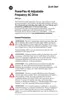
Component Specifications
This option is not compatible with Code S7.
Quick Disconnects
DeviceNet Quick Disconnect - Bottom (Code E22)
A Brad Harrison, 5 pin, bulkhead, male receptacle is provided and wired to
the drive mounted DeviceNet module. The connector is located through the
bottom of the enclosure providing a quick disconnect. This option is
designed to enhance the DeviceNet offering (Position 12, Code D) and is
not compatible with options 4, C, E, P (Position 12), or E23.
To review schematic refer to
Figure 2.4 on page 2-5.
To review layout refer to
Figure 3.4 on page 3-4.
For NEMA/UL Type 4 or less stringent environments, the outer connector
construction is made of plastic designed to withstand washdown conditions.
DeviceNet Quick Disconnect - Left Side (Code E23)
A Brad Harrison, 5 pin, bulkhead, male receptacle is provided and wired to
the drive mounted DeviceNet module. The connector is located through the
left side of the enclosure providing a quick disconnect. This option is
designed to enhance the DeviceNet offering (Position 12, Code D) and is
not compatible with options 4, C, E, P (Position 12), or E22.
To review schematic refer to
Figure 2.4 on page 2-5.
To review layout refer to
Figure 3.4 on page 3-4.
For NEMA/UL Type 4 or less stringent environments the outer connector
construction is made of plastic designed to withstand washdown conditions.
Bulletin 800F
Devices
IEC style, Internationally rated
Meet IP65/IP66 and NEMA/UL Type 4/4X/13
UL Listed, CSA Certified
10 amp contacts
Screw terminals, 0.3–3.5 mm
2
(22–12 AWG) maximum
Clear Fault Push
Button:
Flush head, Black, 1 N.O. contact
Legend Plate 30 x 50 mm, Black with white lettering
Wiring 0.8 mm
2
(18 AWG), Blue
Schematic Figure 2.17 on page 2-18

 Loading...