PowerFlex 40 Standard Configured Drive Standard Features and Options 1-9
Publication 23B-IN001G
Operator Device Options
Hand/Off/Auto Selector Switch (Position 16+, Code S1)
This 800F door mounted operator device is factory installed and provides a
Hand/Off/Auto selector switch.
The Hand/Off/Auto selector switch will start the drive in Hand mode and
stop the drive in Off mode. In Auto mode the drive will be stopped and
started from remote contact closures. In all cases, the Stop input to the drive
must be present before the drive will start.
The Hand/Off/Auto selector switch also determines the source of the
actual drive speed reference. In Hand mode, speed source is parameter
A072 [Preset Freq 2]. In Auto mode, speed source is parameter A071
[Preset Freq 1].
If the door mounted speed potentiometer (Option S18) is supplied and it is
intended to be the speed reference in Hand mode, set parameter A052
[Digital In2 Sel] to option 13 “10V In Ctrl”. Refer to the table below and the
PowerFlex 40 User Manual, publication 22B-UM001, for other options.
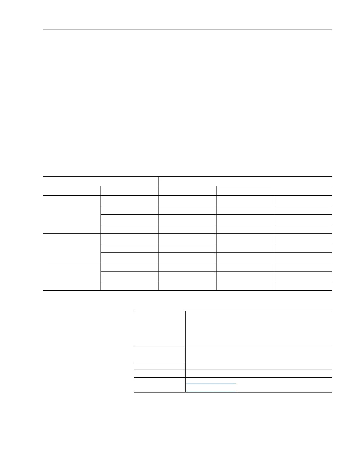
Hand/Off/Auto Selector Switch (Code S1)
Component Specifications
This option is not compatible with Codes R3, R5, S4, S7, S20, S21 or S22.
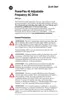
Speed Reference Parameter Settings
Hand Mode Auto Mode P038 [Speed Reference] A051 [Digital In1 Sel] A052 [Digital In2 Sel]
Preset Speed Preset Speed 4 “Preset Freq” 4 “Preset Freq” 4 “Preset Freq”
Analog Input (0-10V) 4 “Preset Freq” 13 “10V In Ctrl” 4 “Preset Freq”
Analog Input (4-20mA) 4 “Preset Freq” 14 “20mA In Ctrl” 4 “Preset Freq”
Communication Port
(1)
4 “Preset Freq” 6 “Comm Port” 4 “Preset Freq”
Speed Pot (Door) Preset Speed 4 “Preset Freq” 4 “Preset Freq” 13 “10V In Ctrl”
Analog Input (4-20mA) 4 “Preset Freq” 14 “20mA In Ctrl” 13 “10V In Ctrl”
Communication Port
(1)
4 “Preset Freq” 6 “Comm Port” 13 “10V In Ctrl”
HIM (Door) Preset Speed 4 “Preset Freq” 4 “Preset Freq” 6 “Comm Port”
Analog Input (0-10V) 4 “Preset Freq” 13 “10V In Ctrl” 6 “Comm Port”
Analog Input (4-20mA) 4 “Preset Freq” 14 “20mA In Ctrl” 6 “Comm Port”
(1)
Communication port will have both logic and reference control.
Bulletin 800F
Devices
IEC style, Internationally rated
Meet IP65/IP66 and NEMA/UL Type 4/4X/13
UL Listed, CSA Certified
10 amp contacts
Screw terminals, 0.3–3.5 mm
2
(22–12 AWG) maximum
Hand/Off/Auto
Selector Switch
3 position, Maintained
4 N.O. contacts
Legend Plate 30 x 50 mm, Black with white lettering
Wiring 0.8 mm
2
(18 AWG), Blue
Schematics Figure 2.4 on page 2-5
Figure 2.5 on page 2-6

 Loading...