Publication 23B-IN001G
3-2 Mechanical Installation
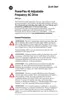
Figure 3.1 Minimum Mounting Clearances
Dimensions are in millimeters and (inches).
Dimensions
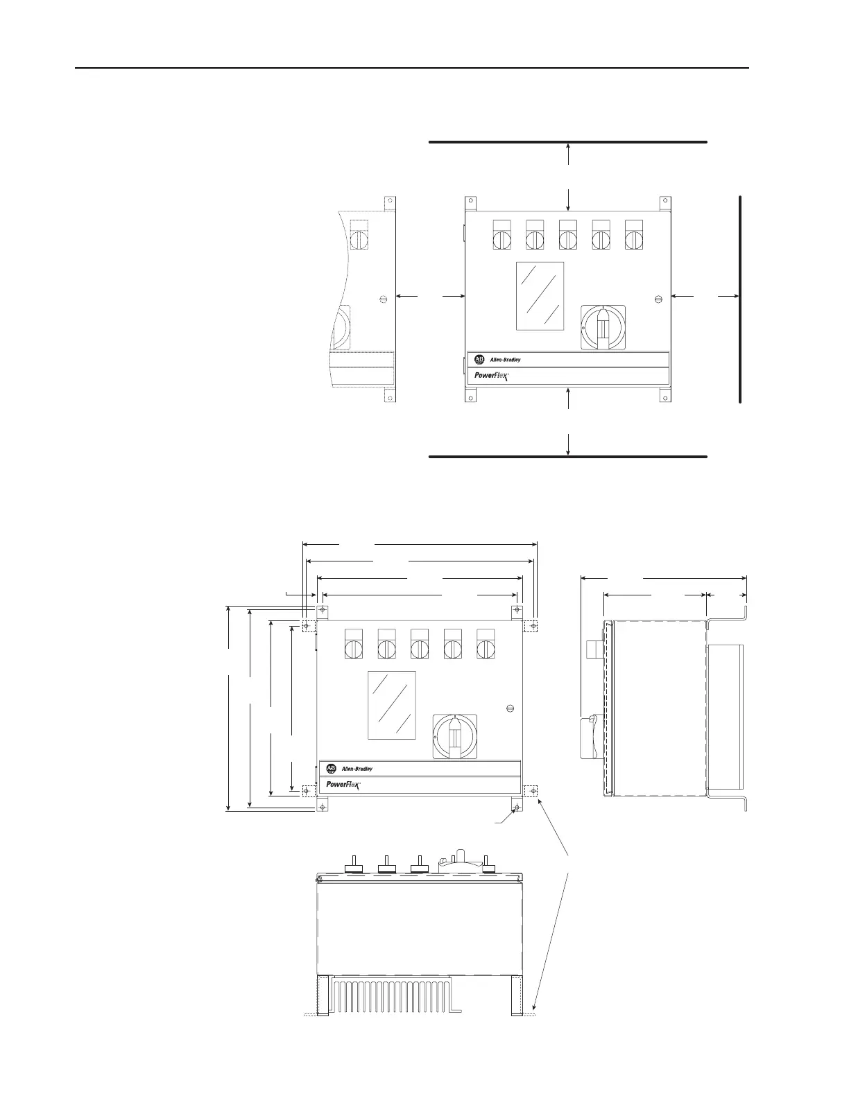
Figure 3.2 Frame B Dimensions
Dimensions are in millimeters and (inches).
ON
F
F
O
152.4
(6.00)
152.4
(6.00)
152.4
(6.00)
152.4
(6.00)
Drive or
other device
ON
F
F
O
355.6
(14.00)
9.4
(0.37)
393.2
(15.48)
405.9
(15.98)
336.6
(13.25)
287.5
(11.32)
177.8
(7.00)
69.3
(2.73)
355.1
(13.98)
342.4
(13.48)
304.8
(12.00)
285.8
(11.25)
Optional mounting bracket orientation.
6.35
(0.25)

 Loading...