51 of 136
50. Use the down arrow and up arrow keys, if necessary, to highlight ‘Par 0050 Anlg In0 Value’. Use the
Enter key to make this your selection. Press the ‘ENTER’ soft key to confirm and save your selection.
51. The next few steps will configure the Analog Input you chose as Speed Reference. For this lab session we will use the
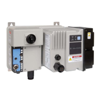
0-10V potentiometer (labeled 0-10VDC IN 0) on the demo as our Analog Input speed reference. Pressing the ‘ENTER’
soft key in the previous step has led you to the first item required to configure the Analog Input. You should be in ‘Edit
Anlg In0 Hi’ screen. Press the ‘ENTER’ soft key to accept the default value of ‘10.000’ Volt.
52. In the ’Edit Anlg In0 Lo’ screen that follows, press the ‘ENTER’ soft key to accept the default value of ‘0.000’ Volt.
53. In the next few screens input these values:
‘Speed Ref A Anlg Hi’= 1600 RPM
‘Speed Ref A Anlg Lo’ = 0 RPM
Press the ‘ENTER’ soft key.
54. You should be in the ‘Startup / Stop Config’ screen now, press the ‘ENTER’ soft key to accept the default selection of
‘Ramp 1’ to be used as ‘Stop Mode A’.
55. Pressing the ‘ENTER’ key in the previous step has directed you to the screen to configure the ‘Bus Reg Mode A’.
Select the default of ‘Adjust Freq 1’ using the ‘ENTER’ soft key.
56. Following the step to set bus regulation you will now set Ramp (Accel and Decel) times. In the ‘Edit Accel Time 1’
screen, use the appropriate number key to enter a value of ‘3’ seconds. Press the ‘ENTER’ soft key.
57. Similarly enter a value of 3 seconds for the deceleration time in the ‘Edit Decel Time 1’ screen. Press the ‘ENTER’ soft
key.
58. The next screen continues the ramp speed configuration and asks the question ‘Do you want to perform S-curve for
Accel/Decel? ‘. We will select ‘No’ as the answer for this lab session. You can select ‘No’ by highlighting it using the
down and up arrow keys and then using the ‘ENTER’ soft key to confirm and save your selection.
Configuring the Inputs and Outputs
59. Completing the previous step successfully has led you to the ‘General Startup Main Menu’ with the item ‘I/O’
highlighted. Press the ‘ENTER’ soft key to enter the ‘I/O’ section.
60. You should be in the ‘Start Stop I/O’ screen now. The first item to configure on this list is ‘Start Stop & Dir’. Press the
‘ENTER’ soft key to enter this section. Read the Introductory screen to this section and press the ‘ENTER’ soft key to
continue.
61. The next screen requires you to answer the question ‘Will a Digital Input be used as a START Source? Select ‘Yes’
using the down and up arrow keys and then using ‘ENTER’ soft key to confirm and save your
selection. We will use the green push button labeled ’IN 1’ in the demo as our Start Source in a later step.
62. The next screen will ask the question ‘Is Reverse required from a digital input?’ Select ‘Yes’ using the down
and up arrow keys and then using ‘ENTER’ soft key to confirm and save your selection. We will use the switch
labeled ’IN 2’ in the demo as forward/reverse in a later step.

 Loading...

