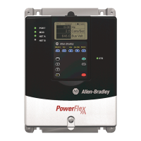
Do you have a question about the Rockwell Automation PowerFlex 700 and is the answer not in the manual?
Explains operational differences of solid-state equipment and responsibilities for application, including warnings.
Introduces the manual's scope, target audience, and excluded information for the drive.
Describes enclosure types (Open-Chassis, Type 1) for PowerFlex 700L drives and mounting requirements.
Details requirements for AC supply systems, including kVA, impedance, and circuit breaker selection.
Covers drive dimensions, required installation space, and clearance requirements for proper mounting.
Provides instructions and safety precautions for safely lifting and handling the drive unit.
Details enclosure design, panel sizing, and fastener specifications for secure drive mounting.
Guides on routing signal, control, and power wiring in separate conduits to prevent interference.
Explains safety ground connection requirements and procedures for ungrounded or resistive grounded systems.
Covers installation of incoming line components, input power, output contactors, and motor wiring.
Details wiring connections for the drive's control terminals, including specific terminal specifications.
Describes control synchronization and DPI communication cable connections for drive modules.
Details DPI port connections, HIM options, and external door-mounted HIM setup.
Describes the composition of Frame 3A and 3B drives, including Input Filter and Power Module Bays.
Illustrates drive dimensions for calculating installation space for Frame 3A and 3B drives.
Specifies minimum clearances for air circulation around drive enclosures for proper ventilation.
Details vertical clearance requirements for power modules to ensure proper airflow and prevent faults.
Emphasizes verifying plant power meets input requirements and matches drive nameplate voltage.
Provides instructions and safety precautions for safely lifting and handling the drive equipment.
Provides instructions for safely removing the pallet and mounting brackets from the drive.
Illustrates instructions for lifting the input filter bay component of the drive.
Shows instructions for lifting the power module, warning against using bus bars for handling.
Details features for attaching support brackets to power modules to prevent mechanical damage.
Explains location and removal of Active Converter and Inverter control cassettes for access to wiring.
Details wiring installation codes, separate conduit routing, and wire chafing prevention for Frame 3A/3B drives.
Details grounding conductors for power modules and input filter bays, and specifies corner grounding rules.
Provides steps for connecting three-phase AC input power leads to drive terminals and tightening connections.
Guides on routing and connecting AC output power wiring from drive terminals to the motor, including conduit rules.
Details control wiring between input filter and power module bays for factory-wired drives.
Explains control synchronization cable connections for Frame 3A and 3B drives.
Details DPI connection points for drives and options for connecting external HIM devices.
Details connecting an optional external door-mounted HIM to the drive's DPI port.
Explains different types of drive cooling loops, including liquid-to-liquid heat exchangers.
Lists recommended liquid-to-liquid heat exchangers from Rockwell Automation based on drive frame size.
Details coolant compatibility, recommended coolants, and corrosion inhibitors for drive loops.
Provides guidelines for applying cooling loops, including temperature ranges, flow switches, and material recommendations.
Explains how to connect coolant inlet and outlet lines for Frame 2, 3A, and 3B drives using flare fittings.
Details specific 700 Vector Control parameters affected by the drive structure.
Lists parameters within the Utility file, specifically for diagnostics and alarms.
Describes parameters related to communication file settings, including DPI port selection and logic masks.
Details specific 700S Phase II Control functions affected when used with the drive structure.
Details drive faults (stopping conditions) and alarms (non-critical issues) with their types and descriptions.
Explains how drive operational states are monitored and indicated via LEDs and the Human Interface Module (HIM).
Provides step-by-step instructions on how to clear drive faults using the HIM or parameter settings.
Lists and describes specific faults related to the 700 Vector Control system, including cause and action.
Lists and describes specific faults related to the 700S Phase II Control system, including cause and action.
Explains that alarms clear automatically when the condition is resolved and describes specific 700S Phase II Control alarms.
Details the procedure for replacing the door filter in the input filter cabinet for specific drive frames.
Details drive specifications such as agency certification, protection parameters, environment, and electrical characteristics.
Provides guidelines for derating drive output current based on altitude, ambient temperature, and carrier frequency.
Lists normal duty and heavy duty drive ratings (continuous, 1-min, 3-sec) for various voltage and frame sizes.
Presents watts loss values for filter, power, and complete drive sections based on rated load, speed, and PWM carrier frequency.
Provides recommended AC line input fuse and circuit breaker information for short circuit protection.
Illustrates the regenerative drive wiring diagram for Frame 2 with TB4 connections (400/480V, 3 Phase).
Illustrates the regenerative drive wiring diagram for Frame 2 without TB4 connections (400/480V, 3 Phase).
Shows the wiring diagram for Frame 3A regenerative drive with 400/480V, 3 Phase configuration.
Shows the wiring diagram for Frame 3A regenerative drive with 600/690V, 3 Phase configuration.
Illustrates the wiring diagram for Frame 3A converter/inverter power module (400/690V, 3 Phase).
Illustrates the wiring diagram for Frame 3A dual inverter power module (400/690V, 3 Phase).
Shows the wiring diagram for Frame 3B regenerative drive with 400/480V, 3 Phase configuration.
Shows the wiring diagram for Frame 3B regenerative drive with 600/690V, 3 Phase configuration.
Presents the schematic for Frame 3B active converter power module (400/690V, 3 Phase).
Presents the schematic for Frame 3B inverter power module (400/690V, 3 Phase).
| Brand | Rockwell Automation |
|---|---|
| Model | PowerFlex 700 |
| Category | Controller |
| Language | English |


