2-8 Frame 2 Installation
PowerFlex® 700L Liquid-Cooled Drive User Manual
Publication 20L-UM001D-EN-P
Removing the Inverter
Control Cassette
For Frame 2 drives, the Inverter is equipped with either the standard
PowerFlex 700 Vector Control cassette or an optional PowerFlex 700S
Phase II Control cassette. In either case, the cassette is removed in the same
way.
PowerFlex 700 Vector Control Cassette (standard)
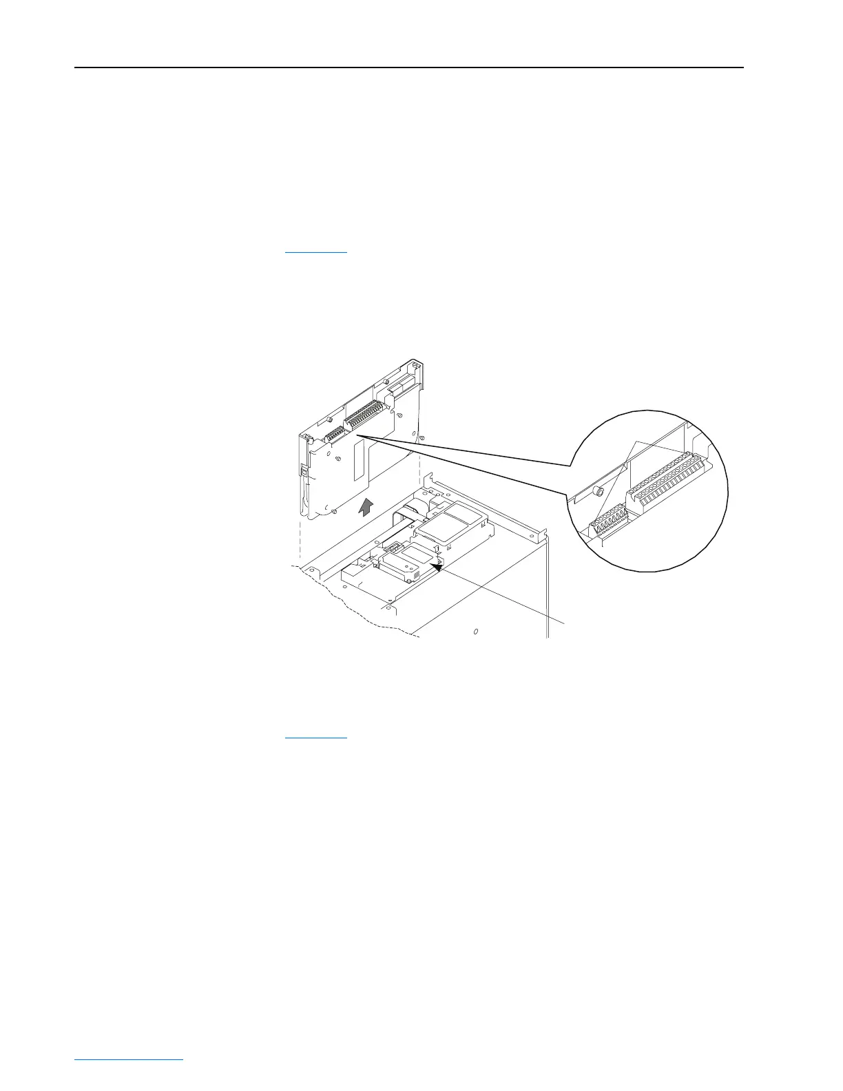
Figure 2.8 shows the location and removal of the drive’s standard
PowerFlex 700 Vector Control cassette to access its terminal blocks for
control wiring. Refer to the PowerFlex 700 Adjustable Frequency AC Drive
User Manual - Series B (publication 20B-UM002) for control wiring
details.
Figure 2.8 Removing the Standard PowerFlex 700 Vector Control Cassette
PowerFlex 700S Phase II Control Cassette (optional)
Figure 2.9 shows the location and removal of the drive’s optional PowerFlex
700S Phase II Control cassette to access its terminal blocks for control
wiring. Please refer to the PowerFlex 700S High Performance AC Drive -
Phase II Control User Manual (publication 20D-UM006) for control wiring
details.
Communications
Adapter Option
Pin 1
Detail
 Loading...


