3-14 Frame 3A and 3B Installation
PowerFlex® 700L Liquid-Cooled Drive User Manual
Publication 20L-UM001D-EN-P
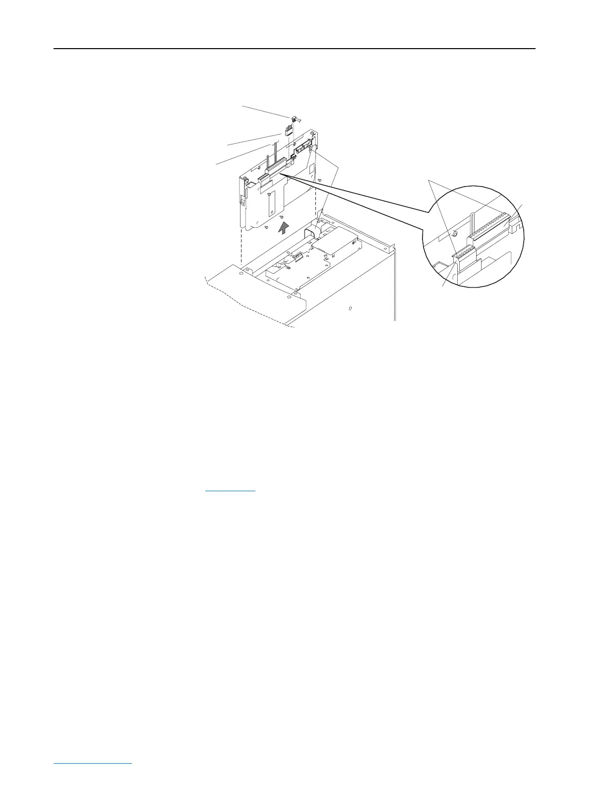
Figure 3.14 Removing the Frame 3B Active Converter Control Cassette
Removing the Inverter
Power Module Control
Cassette
For Frame 3A drives (with a combined Active Converter/Inverter Power
Module) or Frame 3B drives (with a separate Inverter Power Module), the
Inverter is equipped with either the standard PowerFlex 700 Vector Control
cassette or an optional PowerFlex 700S Phase II Control cassette. In either
case, the cassette is removed in the same way.
PowerFlex 700 Vector Control Cassette (standard)
Figure 3.15 shows the location and removal of the Inverter Power Module’s
standard PowerFlex 700 Vector Control cassette to access its terminal
blocks for control wiring. Please refer to the PowerFlex 700 Adjustable
Frequency AC Drive User Manual - Series B (publication 20B-UM002) for
control wiring details.
Internal DPI Cable
40-Pin
Ribbon Cable
Synchronization Cable
(For use with coupled Inverter Power
Modules with 700 Vector Control only)
Synchronization Cable
(For use with coupled Inverter Power
Modules with 700S Phase II Control only)
P2
Pin 1
Detail
P1
 Loading...


