6-2 Troubleshooting
PowerFlex® 700L Liquid-Cooled Drive User Manual
Publication 20L-UM001D-EN-P
Accessing Status Indicators of Powered Frame 3A and 3B Complete
Drives
Status indicators (shown in Table 6.A) for Frame 3A and 3B complete
drives are inside the power module bay. To access the status indicators,
follow the instructions below.
To Open:
1. Unlock the input filter bay door and the power module bay door using
the key provided with the drive.
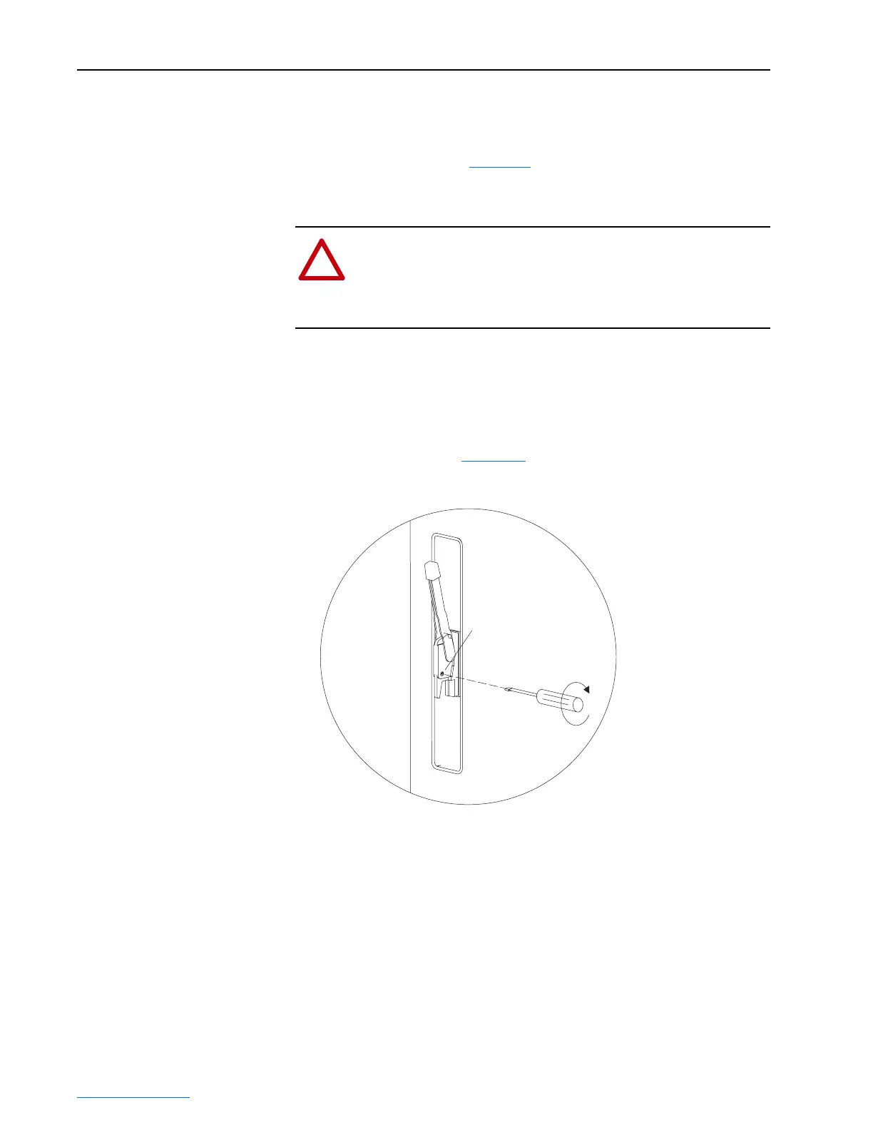
2. Turn the circuit breaker handle door locking mechanism release using a
flat head screwdriver (Figure 6.1
) to unlatch the input filter bay door.
Figure 6.1 Releasing Door Locking Mechanism
3. Swing open the input filter bay several inches until the door interlock
mechanism unlatches from the power module bay door.
4. Swing open the power module bay door to view the status indicators on
the power module(s).
To Close:
1. Close and lock the power module bay door.
2. Close and lock the input filter bay door.
!
ATTENTION: Risk of injury or death exists. Only qualified
electricians should use this procedure. Bypassing the interlock
mechanism exposes the user to dangerous high voltage live
components. Failure to comply may result in personal injury and/
or death.
Circuit Breaker Handle
Door Locking Mechanism
Release
 Loading...


