3-34 Frame 3A and 3B Installation
PowerFlex® 700L Liquid-Cooled Drive User Manual
Publication 20L-UM001D-EN-P
Synchronization
Connections for Frame 3A
Coupled Power Modules
Frame 3A combined Converter/Inverter Power Modules are only configured
as coupled power modules. Coupling the Converter and Inverter is achieved
by using two factory-installed cables: a control synchronization cable and
an inverter-to-converter DPI communication cable. The two cables are
described in the next two subsections.
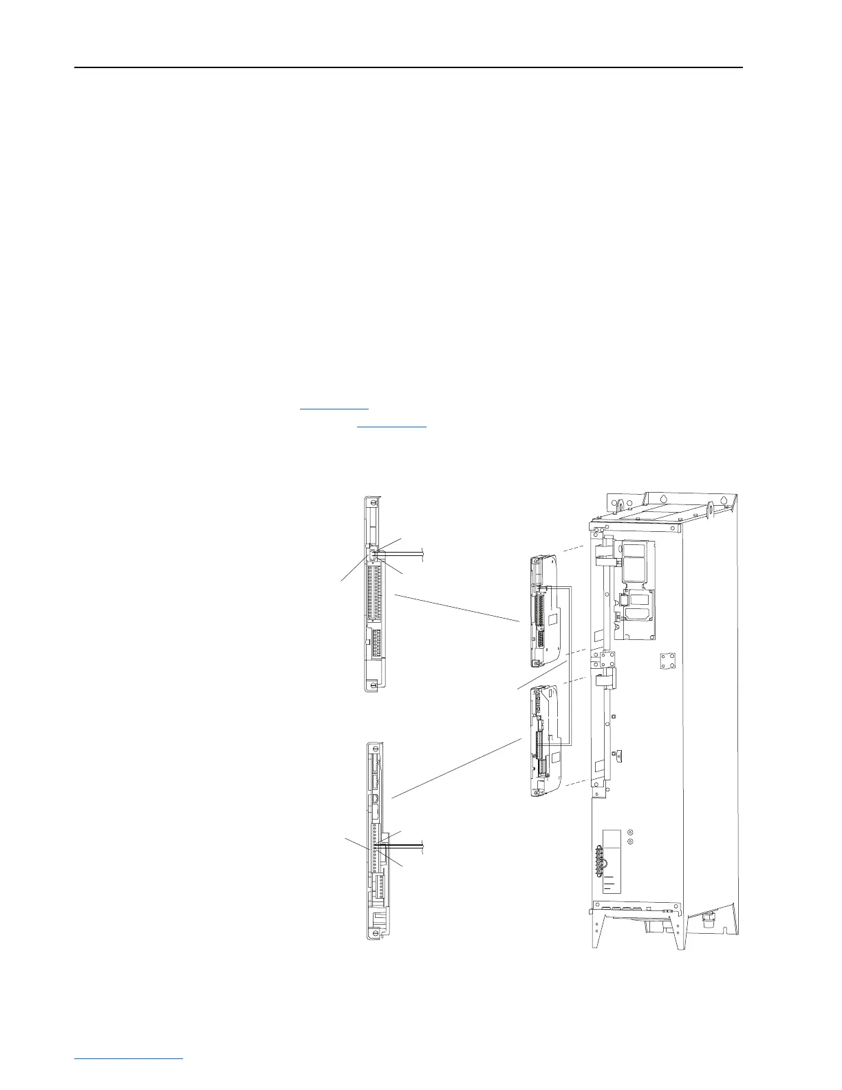
Control Synchronization Cable
To enable synchronization between the Inverter control printed circuit board
and the Converter control printed circuit board, a factory-installed control
synchronization cable connects each board. No user connection is required.
However, the connection method is different for PowerFlex 700L
Liquid-Cooled AC drives with 700 Vector Control and 700S Phase II
Control. The 700 Vector Control synchronization cable connection is shown
in Figure 3.31
. The 700S Phase II Control synchronization cable connection
is shown in Figure 3.32
.
Figure 3.31 Frame 3A 700 Vector Control Synchronization Cable Connection
TB2 Header on
700 Vector
Control Cassette
P1 Terminal Block
on Active Converter
Control Cassette
TB2-2
TB2-1
P1-7
1
P1-8
15
SHLDSHLD
24 VDC
DC POSITIVE
DC NEGATIVE
1 120 VAC
2 PRECHARGE COIL
6 INDUCTOR OVERTEMP
WIRE RANGE:
24-10 AWG
(0.2-4 MM)
4 CHARGE FEEDBACK
GATE ENABLE
STRIP LENGTH:
0.31 IN (8 MM)
TORQUE:
8 IN-LB
(0.9 N-M)
Control Synchronization
Cable (Factory-Installed)
 Loading...


