Programming and Parameters 5-5
PowerFlex® 700L Liquid-Cooled Drive User Manual
Publication 20L-UM001D-EN-P
Affected 700S Phase II
Control Parameters
When a PowerFlex 700L Liquid-Cooled drive is present, the following
700S Phase II Control functions are affected:
• Supports DPI communications ports 1 through 6.
• Supports DPI Type III communications with an active converter.
• Supports the power structure fault latch and multiple NTCs.
• Supports IT (Junction Temperature Calculation) mode.
• Bus regulator mode is disabled when an active converter is present.
• Fast Flux-up current is limited to 40% of motor nameplate current
instead of 70% (PowerFlex 700S).
Utility File
In the Utility file - Diagnostics group, the following parameters are
available when a PowerFlex 700L Liquid-Cooled AC drive is present.
No.
Name
Description
Values
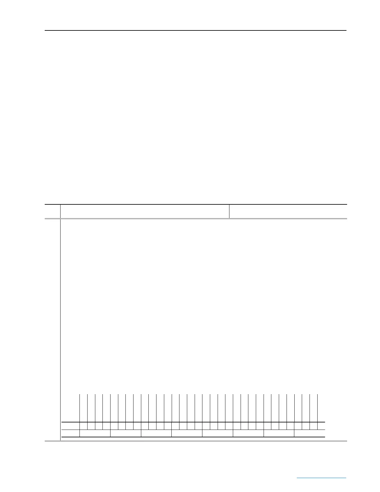
332 700L EventStatus
Indicates the presence of certain drive anomalies for the PowerFlex 700L Liquid-Cooled drive.
Bit 0 [Dsat Phs U1] indicates that the primary structure detected a Dsat on phase U.
Bit 1 [Dsat Phs V1] indicates that the primary structure detected a Dsat on phase V.
Bit 2 [Dsat Phs W] indicates that the primary structure detected a Dsat on phase W.
Bit 3 [Ovr Current1] indicates that the primary structure detected an over current.
Bit 4 [Ovr Volt1] indicates that the primary structure detected an over voltage.
Bit 5 [Asym DcLink1] indicates that the primary structure detected an unbalanced DC Link.
Bit 6 [Pwr Suply1]indicates that the primary structure detected a power supply failure.
Bit 7 [HW Disable1] indicates that the primary structure detected a hardware disable.
Bit 8 [Latch Err1] indicates that the primary structure fault was generated but no indicating bit was set.
Bit 9 [Fan Fail1] indicates
Bit 12 [NonCnfgAlarm] indicates
Bit 13 [Cnv Faulted] indicates
Bit 14 [Cnv NotLogin] indicates the converter was expected but none logged in.
Bit 15 [Cnv NotStart] indicates the converter was commanded to start but did not become active.
Bit 16 [Dsat Phs U2] indicates the second structure detected a Dsat on phase U.
Bit 17 [Dsat Phs V2] indicates the second structure detected a Dsat on phase V.
Bit 18 [Dsat Phs W2] indicates the second structure detected a Dsat on phase W.
Bit 19 [Ovr Current2] indicates the second structure detected an over current.
Bit 20 [Ovr Volt2] indicates the second structure detected an over voltage.
Bit 21 [Asym DcLink2] indicates the second structure detected an unbalanced DC Link.
Bit 22 [Pwr Suply2] indicates the second structure detected a power supply failure.
Bit 23 [HW Disable2] indicates the second structure detected a hardware disable.
Bit 24 [Latch Err2] indicates the second structure fault was generated but no indicating bit was set.
Bit 25 [Fan Fail2] indicates
Note: This parameter was added for firmware version 2.03.
Bit
Definition
Reserved
Reserved
Reserved
Reserved
Reserved
Reserved
Fan Fail2
Latch Err2
HW Disable2
Pwr Suply2
Asym DcLink2
Ovr Volt2
Ovr Current2
Dsat Phs W2
Dsat Phs V2
Dsat Phs U2
Cnv NotStart
Cnv NotLogin
Cnv Faulted
NonCnfgAlarm
Reserved
Reserved
Fan Fail1
Latch Err1
HW Disable1
Pwr Suply1
Asym DcLink1
Ovr Volt1
Ovr Current1
Dsat Phs W1
Dsat Phs V1
Dsat Phs U1
Default00000000000000000000000000000000
Bit 313029282726252423222120191817161514131211109 8 7 6 5 4 3 2 1 0
0 = False
1 = True
 Loading...


