3-2 Frame 3A and 3B Installation
PowerFlex® 700L Liquid-Cooled Drive User Manual
Publication 20L-UM001D-EN-P
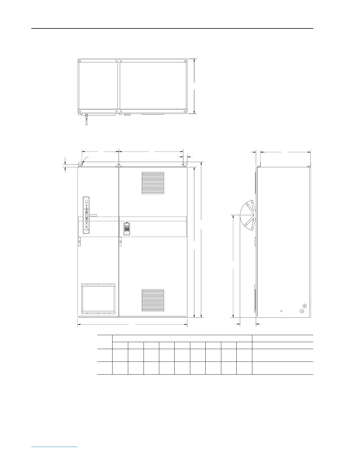
Figure 3.1 Frame 3 Complete Drive Installation Dimensions
Recommended Air Flow Clearances for Complete Drive
Be sure there is adequate clearance for air circulation around the drive
enclosures. A 15 cm (6-in.) minimum clearance is required wherever vents
are located in the cabinet.
Dimensions are in millimeters and (inches).
C
GH
J
D Max.
F Max.
E
B
A
INPUT
FILTER BAY
POWER
MODULE BAY
61 (2.39)
65 (2.56)
38
(1.50)
Ø
35 (
Ø
1.38)
OUTLET
INLET
Frame
Size
Dimensions Approximate Weight kg (lbs.)
A B C D E F G H J Complete Drive
3A 1200
(47.2)
2000
(78.7)
600
(23.6)
2078
(81.9)
1500
(59.1)
233
(9.2)
542
(21.3)
542
(21.3)
535
(21.1)
950 (2090)
3B 1600
(63.0)
2200
(86.6)
800
(31.5)
2278
(89.8)
1500
(59.1)
233
(9.2)
542
(21.3)
942
(37.1)
735
(28.9)
1361 (3000)
 Loading...


