Frame 3A and 3B Installation 3-15
PowerFlex® 700L Liquid-Cooled Drive User Manual
Publication 20L-UM001D-EN-P
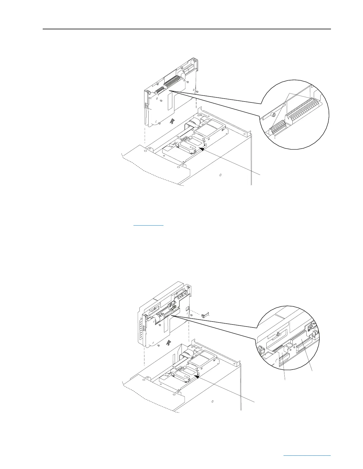
Figure 3.15 Removing the Standard PowerFlex 700 Vector Control Cassette
PowerFlex 700S Phase II Control Cassette (optional)
Figure 3.16 shows the location and removal of the Inverter Power Module’s
optional PowerFlex 700S Phase II Control cassette to access its terminal
blocks for control wiring. Please refer to the PowerFlex 700S High
Performance AC Drive - Phase II Control User Manual (publication
20D-UM006) for control wiring details.
Figure 3.16 Removing the Optional PowerFlex 700S Phase II Control Cassette
Communications
Adapter Option
Frame 3B Inverter Power Module shown
Pin 1
Detail
TB2 Terminals
TB1 Terminals
Detail
Communications
Adapter Option
Frame 3B Inverter Power Module shown
 Loading...


