PowerFlex® 700L Liquid-Cooled Drive User Manual
Publication 20L-UM001D-EN-P
Chapter 4
Cooling Loop Installation
Proper liquid cooling is critical to drive operation and reliability. This
chapter provides information about the types of drive cooling loops, drive
coolant requirements, and cooling loop connections for the PowerFlex 700L
Liquid-Cooled drive power structure.
Explanation of Cooling
Loop Types
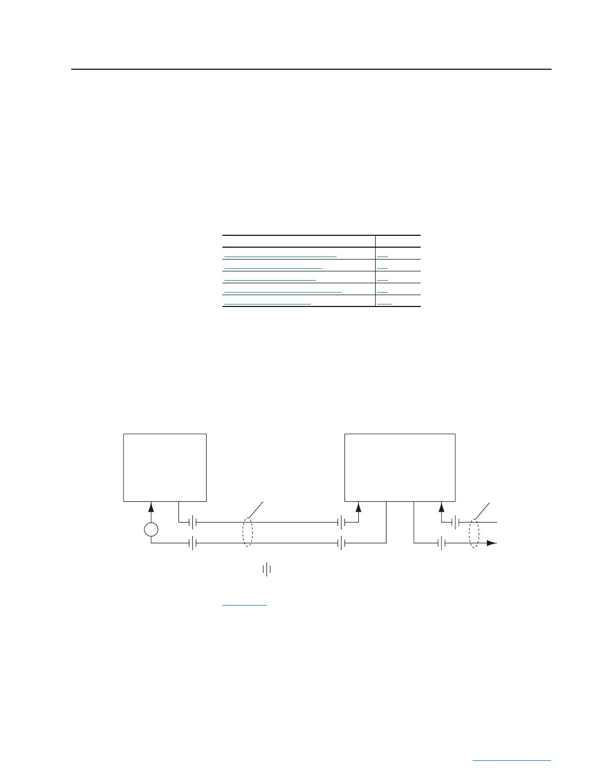
Liquid-to-Liquid Heat Exchanger
The liquid to liquid heat exchanger utilizes a heat transfer plate to transfer
heat from one liquid to another. This method requires a stable water supply
from the user.
Figure 4.1 Drive and Liquid-to-Liquid Heat Exchanger Plumbing Arrangement
Figure 4.2 shows a cooling loop diagram for a typical liquid-to-liquid heat
exchanger.
For information on … See page…
Explanation of Cooling Loop Types
4-1
Recommended Cooling Loops 4-5
Drive Coolant Requirements 4-7
Cooling Loop Application Guidelines 4-9
Drive Coolant Connections 4-10
PowerFlex 700L
Drive
Inlet
Drive
Outlet
Hose Kit
= hose or pipe connection
To Facility Wate
To
Drive
Inlet
From
Drive
Outlet
Return
To
Supply
In
From
Supply
Liquid-to-Liquid
Heat Exchanger
Customer
Supplied Piping
Flow
Indicator
 Loading...


