Frame 3A and 3B Installation 3-17
PowerFlex® 700L Liquid-Cooled Drive User Manual
Publication 20L-UM001D-EN-P
Frame 3B Drives
Figure 3.19 shows the location of Frame 3B Input Filter Bay wire routing.
Figure 3.20
shows locations for Frame 3B Power Module control wire
routing, DPI communications ports/cable routing, and coolant connections.
Figure 3.21
shows locations of Frame 3B complete drive control, ground,
drive input, motor output, and coolant connections.
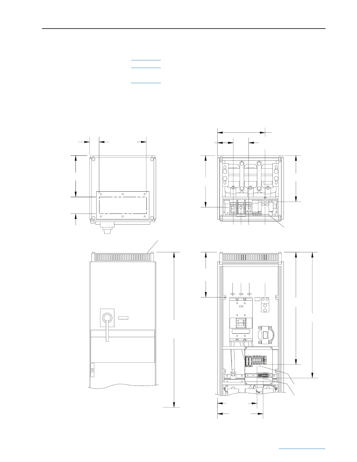
Figure 3.17 Location of Frame 3A Input Filter Bay Wire Routing
432 (17.00)
Cable Opening
Under Cover
87 (3.43)
379 (14.92)
Dimensions are in millimeters and (inches).
152 (6.00)
Cable Opening
Under Cover
Field-Installed
Vented Top Cover
146 (5.74)
473 (18.64)
2092 (82.35)
Maximum
Installed Height
413 (16.25)
1027 (40.43)
1150 (45.27)
362 (14.26)
418 (16.46)
423 (16.67)
436 (17.18)
70 (2.75)
2 Places
PE
L1 L2 L3
PE
L1 L2 L3
FU7, FU8, FU9, TB2
FU7, FU8, FU9
TB2
INSTALLED VIEWS CUTAWAY VIEWS
 Loading...


