2-2 Frame 2 Installation
PowerFlex® 700L Liquid-Cooled Drive User Manual
Publication 20L-UM001D-EN-P
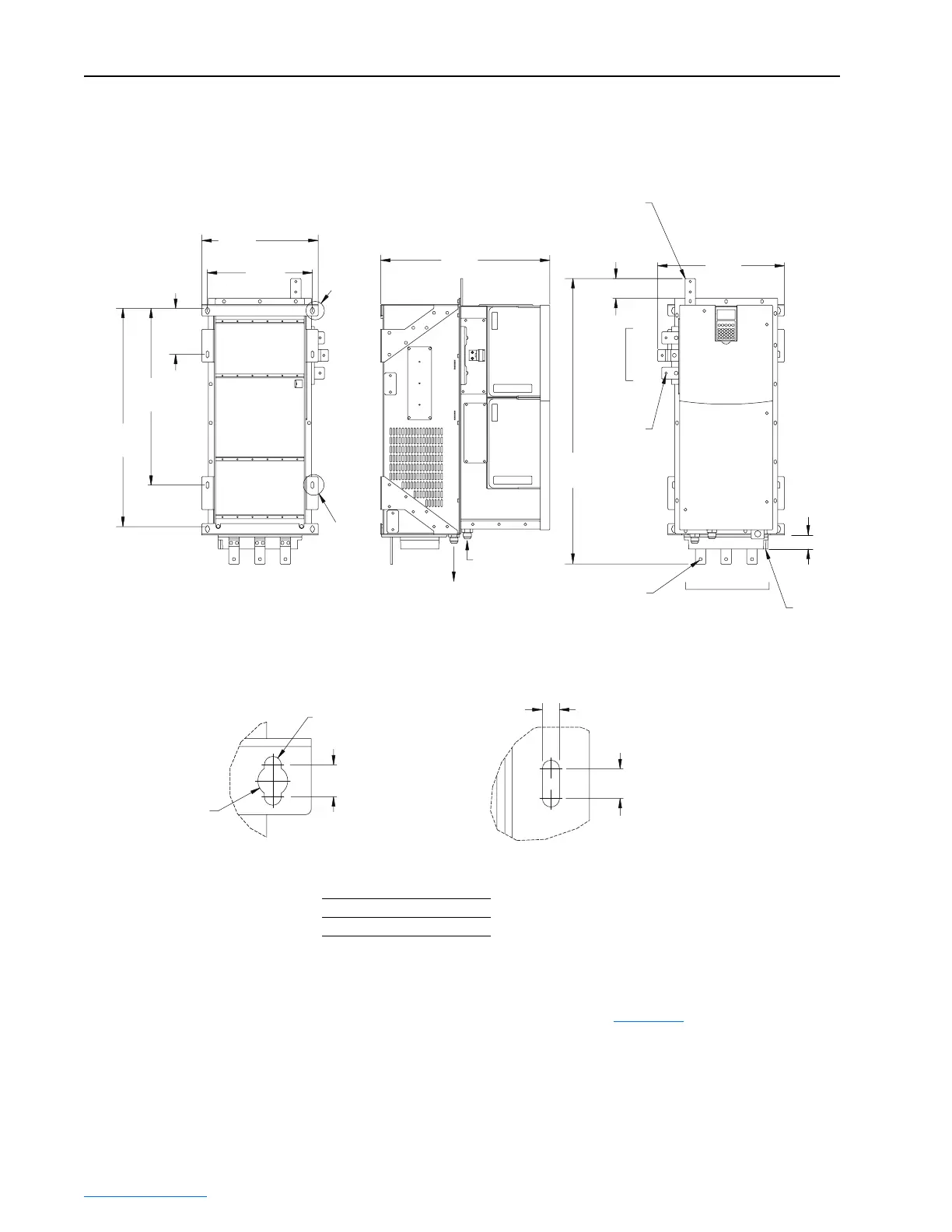
Figure 2.1 Frame 2 Drive Installation Dimensions
Recommended Mounting Clearances
Specified vertical clearance requirements (Figure 2.2) are intended to be
from drive to drive. Other objects can occupy this space; however, reduced
air flow may cause protection circuits to fault the drive. In addition, inlet air
temperature must not exceed the product specification.
46.9
(1.85)
66.6
(2.62)
423.8
(16.68)
955.7
(37.63)
Coolant Inlet
37 Deg Flare -12
Coolant Outlet
37 Deg Flare -12
566.1
(22.29)
389.6
(15.34)
351.0
(13.82)
153.8
(6.06)
591.2
(23.28)
730.2
(28.75)
See
DETAIL
A
See
DETAIL
B
DETAIL A DETAIL B
Ground Terminal
with 2 Clearance
Holes for M8 Stud
3x Clearance
Hole for
M8 Stud
W/T3
V/T2
U/T1
Motor
Output
Terminals
Stirring
Fan
Housing
4x Ø
8.5 (0.33)
4x Ø
15.0 (0.59)
16.0 (0.63)
4x
14.9 (0.59)
4x
8.6 (0.34)
4x
BACK VIEW SIDE VIEW FRONT VIEW
R/L1 S/L2 T/L3
AC Input Terminals
3x Clearance
Hole for
M8 Stud
Dimensions are in millimeters and (inches).
Approximate Weight kg (lbs.)
186 (410)
 Loading...


