2-16 Frame 2 Installation
PowerFlex® 700L Liquid-Cooled Drive User Manual
Publication 20L-UM001D-EN-P
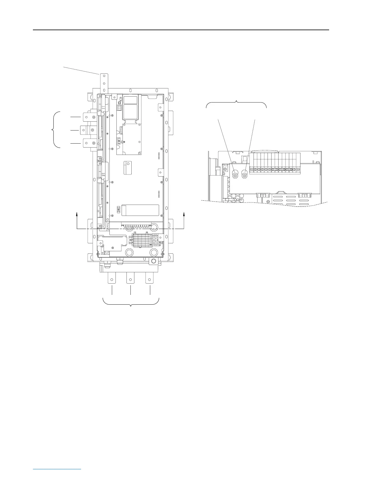
Figure 2.15 Frame 2 Drive Power Terminal Locations
Installing Mechanical Motor Overload Protection (Optional)
To provide the motor with overload protection, local, national, and
international codes (e.g., NEC/CEC) may require one of the following:
• a motor thermostat be installed internal to the motor.
• a mechanical thermal motor overload relay, sized to protect the motor, be
installed between the motor and the drive’s output terminals.
In multiple motor applications (V/Hz regulation only), each motor must
have its own user-supplied overload and branch circuit protection.
AA
Section A-A
W/T3
DC+
Testpoint
DC-
Testpoint
V/T2
U/T1
➋
T/L3S/L2R/L1
➊
➌
➍
 Loading...


