Frame 2 Installation 2-9
PowerFlex® 700L Liquid-Cooled Drive User Manual
Publication 20L-UM001D-EN-P
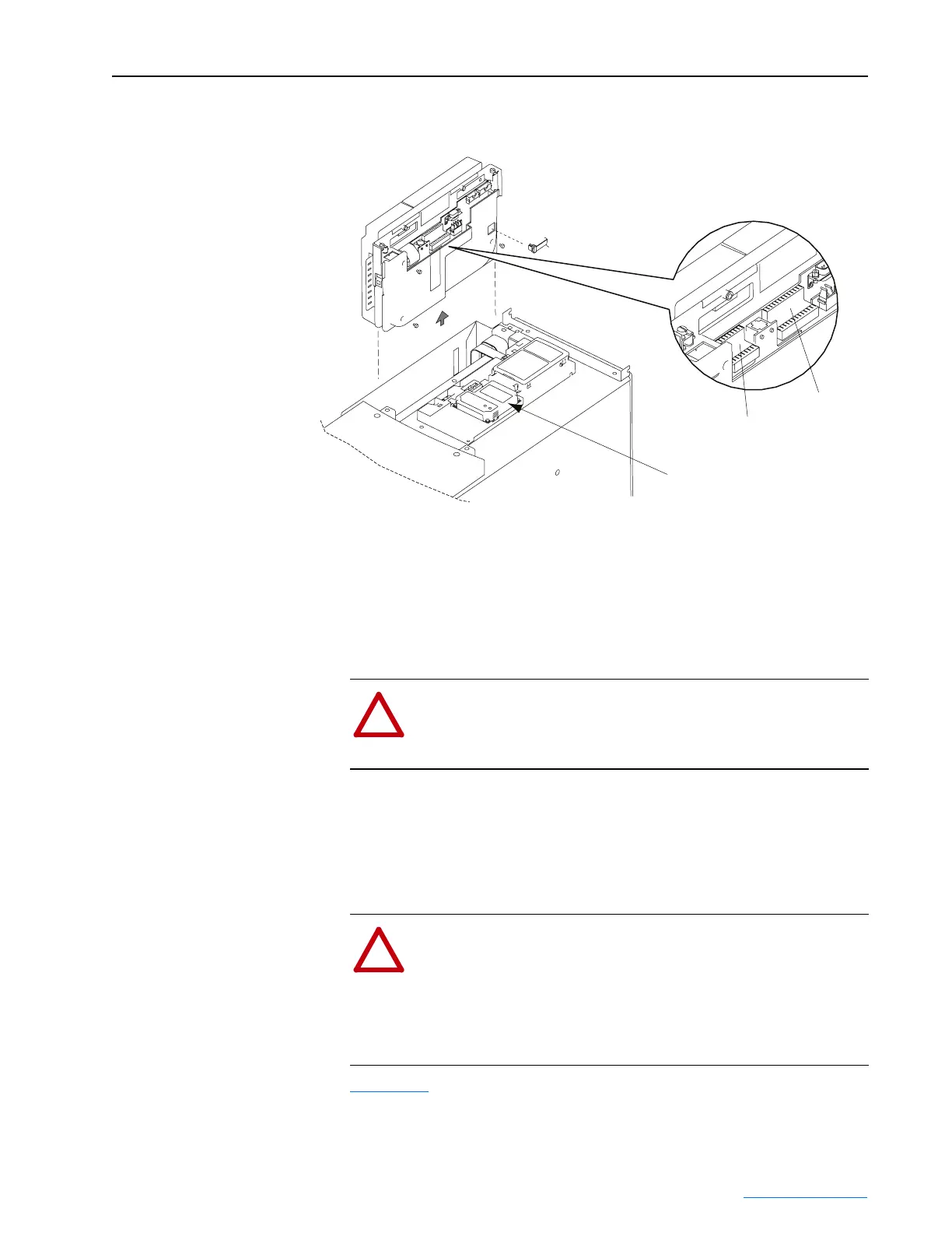
Figure 2.9 Removing the Optional PowerFlex 700S Phase II Control Cassette
Determining Wire Routing
for Control, Ground, Drive
Input, and Motor Output
All wiring should be installed in conformance with the applicable local,
national, and international codes (e.g., NEC/CEC). Signal wiring, control
wiring, and power wiring must be routed in separate conduits to prevent
interference with drive operation. Use grommets, when hubs are not
provided, to guard against wire chafing.
Do not route more than three sets of motor leads through a single conduit.
This will minimize cross-talk that could reduce the effectiveness of noise
reduction methods. If more than three drive/motor connections per conduit
are required, shielded cable must be used. If possible, each conduit should
contain only one set of motor leads.
Figure 2.10 shows locations for Frame 2 control wire routing, ground, drive
input, motor output, DPI communications ports/cable routing, and coolant
connections.
TB2 Terminals
TB1 Terminals
Detail
Communications
Adapter Option
!
ATTENTION: Do not route signal and control wiring with
power wiring in the same conduit. This can cause interference
with drive operation. Failure to observe this precaution could
result in damage to, or destruction of, the equipment.
!
ATTENTION: Unused wires in conduit must be grounded at
both ends to avoid a possible shock hazard caused by induced
voltages. Also, if a drive sharing a conduit is being serviced or
installed, all drives using this conduit should be disabled to
eliminate the possible shock hazard from cross-coupled motor
leads. Failure to observe these precautions could result in bodily
injury.
 Loading...


