2-10 Frame 2 Installation
PowerFlex® 700L Liquid-Cooled Drive User Manual
Publication 20L-UM001D-EN-P
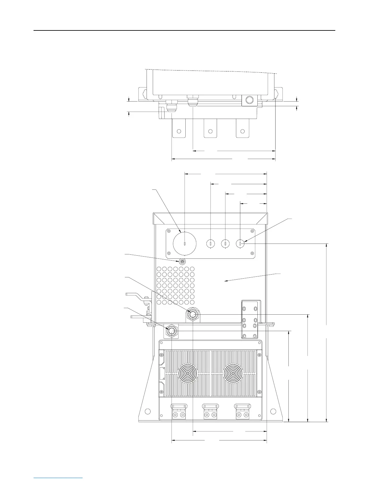
Figure 2.10 Frame 2 Drive Locations for Control Wire Routing, DPI Communications
Port, and Coolant Connections
223.2
(8.79)
280.5
(11.04)
72.0
(2.83)
112.0
(4.41)
152.0
(5.98)
222.0
(8.74)
481.8
(18.97)
245.8
(9.68)
290.4
(11.43)
199.9
(7.87)
257.1
(10.12)
12.6
(0.50)
28.0
(1.10)
Coolant Inlet
Coolant Outlet
Bottom View
of Drive
R/L1 S/L2 T/L3
Control Wire
Conduit Plug
62.7 (2.47) Dia.
Control Wire
Conduit Plug
22.2 (0.87) Dia.
Bottom Drive Cover
DPI Communications
Port
Dimensions are in millimeters and (inches).
 Loading...


