PowerFlex® 700L Liquid-Cooled Drive User Manual
Publication 20L-UM001D-EN-P
Appendix C
Frame 3A and 3B Schematics
Schematics on the following pages illustrate the Frame 3A and Frame 3B
PowerFlex Liquid-Cooled drives and power modules.
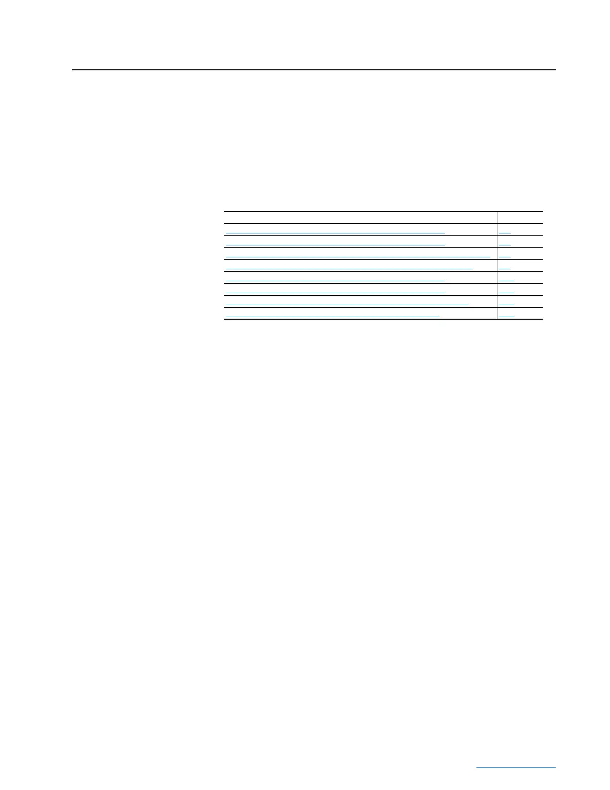
For information on… See page…
Frame 3A Regenerative Drive Wiring Diagram – 400/480V, 3 Phase
C-2
Frame 3A Regenerative Drive Wiring Diagram – 600/690V, 3 Phase C-4
Frame 3A Converter/Inverter Power Module Wiring Diagram – 400/690V, 3 Phase C-6
Frame 3A Dual Inverter Power Module Wiring Diagram – 400/690V, 3 Phase C-8
Frame 3B Regenerative Drive Wiring Diagram – 400/480V, 3 Phase C-10
Frame 3B Regenerative Drive Wiring Diagram – 600/690V, 3 Phase C-12
Frame 3B Active Converter Power Module Schematic – 400/690V, 3 Phase C-14
Frame 3B Inverter Power Module Schematic – 400/690V, 3 Phase C-16
 Loading...


