Frame 2 Installation 2-3
PowerFlex® 700L Liquid-Cooled Drive User Manual
Publication 20L-UM001D-EN-P
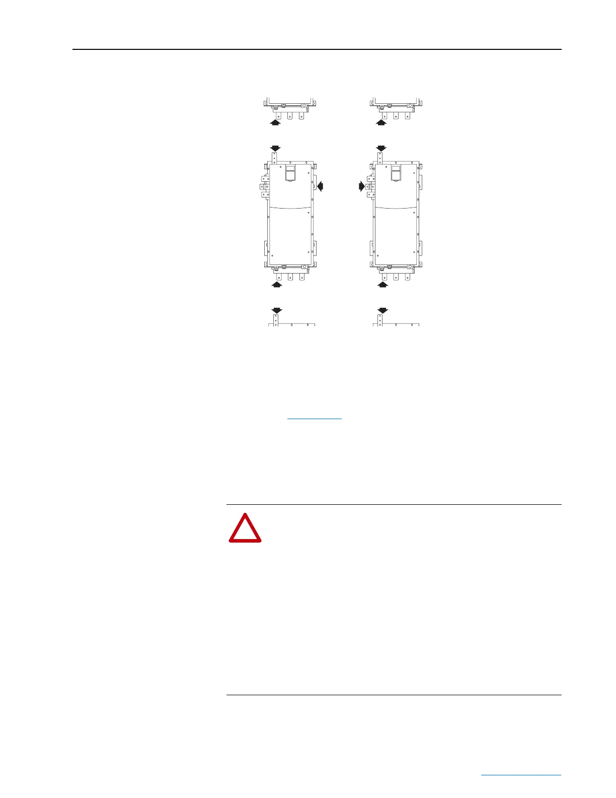
Figure 2.2 Frame 2 Drive Minimum Mounting Clearances
Verifying Drive Input Ratings Match Supplied Power
It is important to verify that plant power will meet the input power
requirements of the PowerFlex 700L Liquid-Cooled Frame 2 drive’s
circuitry. See Appendix
A for input power rating specifications. Be sure
input power to the drive corresponds to the drive nameplate voltage and
frequency.
Equipment Lifting
This section explains how to lift the drive.
101.6 mm
(4.0 in.)
101.6 mm
(4.0 in.)
101.6 mm
(4.0 in.)
101.6 mm
(4.0 in.)
101.6 mm
(4.0 in.)
!
ATTENTION: To guard against possible personal injury and/or
equipment damage…
• Do not allow any part of the drive or lifting mechanism to
make contact with electrically charged conductors or
components.
• At no time should a person or their limbs be directly
underneath the items being lifted.
• Do not subject the load to high rates of acceleration or
deceleration.
• Inspect all lifting hardware for proper attachment before
lifting any drive unit.
 Loading...


