Frame 3A and 3B Installation 3-39
PowerFlex® 700L Liquid-Cooled Drive User Manual
Publication 20L-UM001D-EN-P
External Door-Mounted HIM Connection (optional)
For complete drives, the door-mounted HIM is standard equipment.
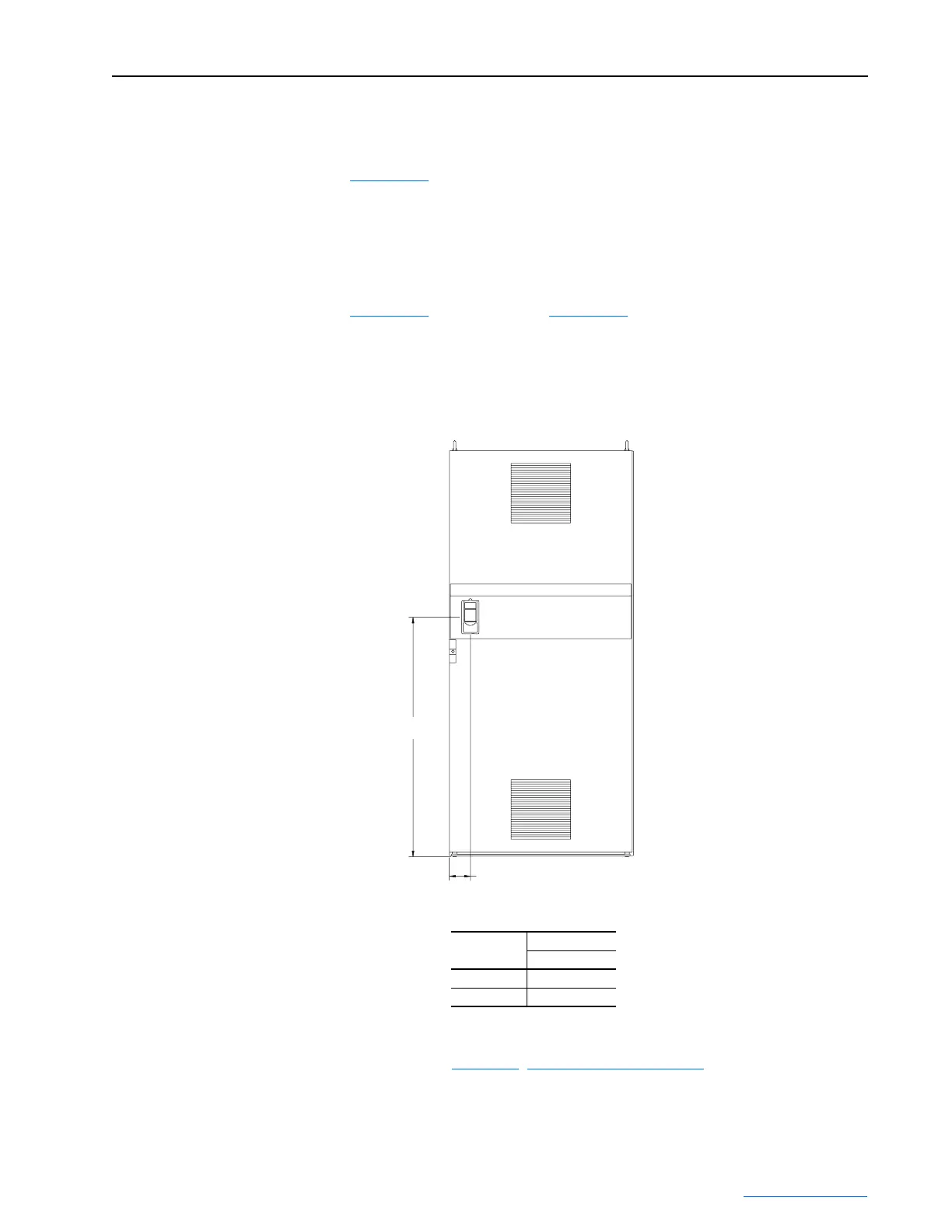
Figure 3.37
shows the location for the door mount bezel in the door of the
Power Module Bay.
For power modules installed in user-supplied enclosures, an optional
external door-mounted HIM may be connected as an alternative to the
external HIM option. The cable supplied with the door-mount HIM option
kit connects to the DPI port on the bottom of the Power Module (see
Figure 3.35
for Frame 3A or Figure 3.36 for Frame 3B). For additional
installation information, refer to the instructions provided with the
door-mount HIM option kit.
Figure 3.37 Complete Drive External Door-Mounted HIM Location
Coolant Loop Connections
Please refer to Chapter 4, Cooling Loop Installation for details.
Frame Size
Dimensions
A
3A 1206 (47.49)
3B 1301 (51.21)
Dimensions are in millimeters and (inches)
116 (4.57)
A
 Loading...


