3-36 Frame 3A and 3B Installation
PowerFlex® 700L Liquid-Cooled Drive User Manual
Publication 20L-UM001D-EN-P
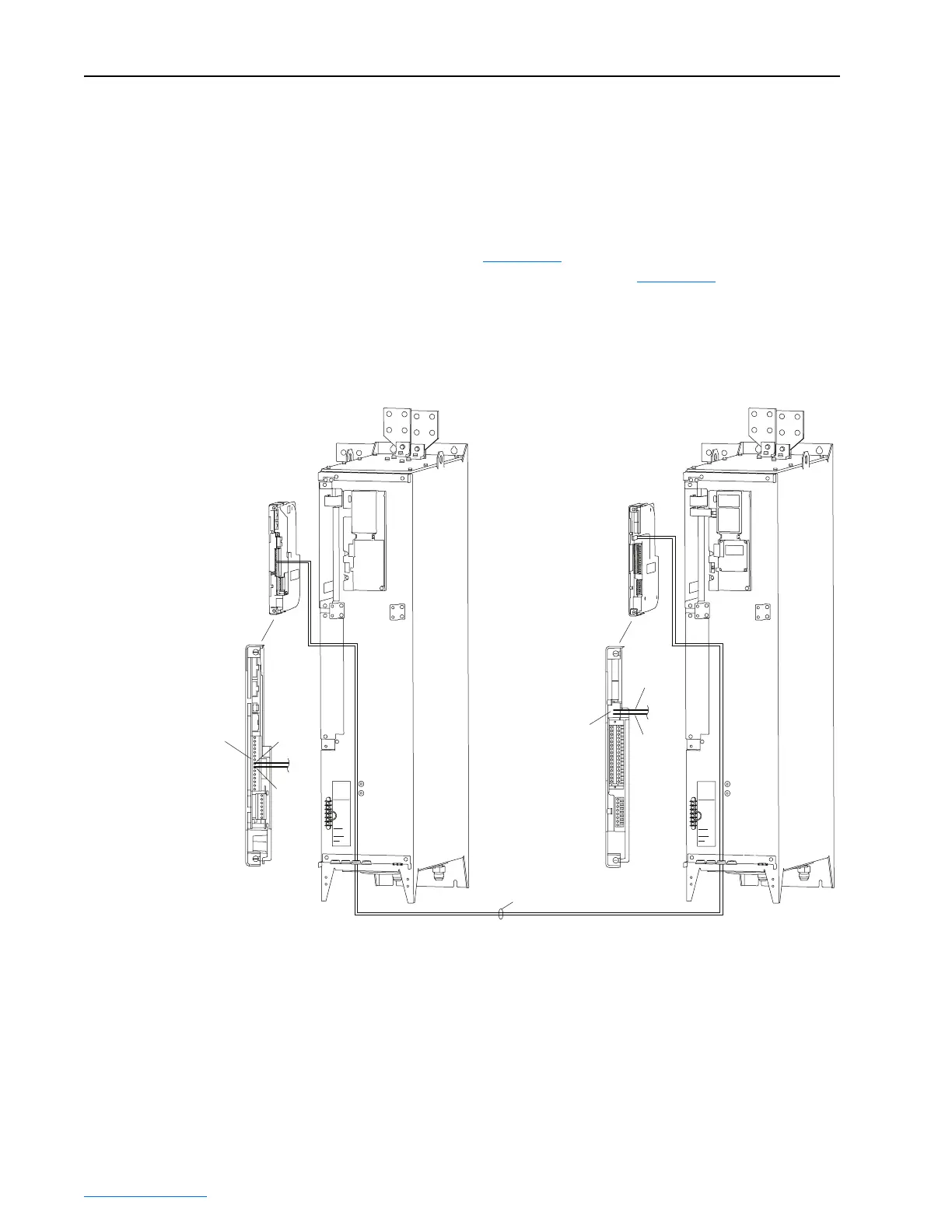
Control Synchronization Cable
To enable synchronization between the Inverter control printed circuit board
and the Converter control printed circuit board, you must connect a
synchronization cable to each board. The connection method is different for
PowerFlex 700L Liquid-Cooled AC drives with 700 Vector Control and
700S Phase II Control. The 700 Vector Control synchronization cable
connection is shown in Figure 3.33
. The 700S Phase II Control
synchronization cable connection is shown in Figure 3.34
. The appropriate
version of the cable is provided in a plastic bag with each Inverter Power
Module. Only one Inverter Power Module may be coupled to a Converter
Power Module.
Figure 3.33 Frame 3B 700 Vector Control Synchronization Cable Connection
1
15
P1 Terminal Block for
Control Synchronization
Cable Connection
TB2 Header for
Control Synchronization
Cable Connection
Control Synchronization Cable
(Factory-Provided)
Active Converter Power Module Inverter Power Module
P1-7
TB2-2
TB2-1
P1-8
Active Converter
Control Cassette
700 Vector
Control Cassette
24 VDC
DC POSITIVE
DC NEGATIVE
1 120 VAC
2 PRECHARGE COIL
6 INDUCTOR OVERTEMP
WIRE RANGE:
24-10 AWG
(0.2-4 MM)
4 CHARGE FEEDBACK
GATE ENABLE
STRIP LENGTH:
0.31 IN (8 MM)
TORQUE:
8 IN-LB
(0.9 N-M)
24 VDC
DC POSITIVE
DC NEGATIVE
1 120 VAC
2 PRECHARGE COIL
6 INDUCTOR OVERTEMP
WIRE RANGE:
24-10 AWG
(0.2-4 MM)
4 CHARGE FEEDBACK
GATE ENABLE
STRIP LENGTH:
0.31 IN (8 MM)
TORQUE:
8 IN-LB
(0.9 N-M)
 Loading...


